Opened 10 years ago
Closed 6 years ago
#477 closed defect (fixed)
cartoon: some tube-coil joins not so hot
| Reported by: | Elaine Meng | Owned by: | Tom Goddard |
|---|---|---|---|
| Priority: | major | Milestone: | 1.0 |
| Component: | Depiction | Version: | |
| Keywords: | Cc: | Eric Pettersen | |
| Blocked By: | Blocking: | ||
| Notify when closed: | Platform: | all | |
| Project: | ChimeraX |
Description
Some of the tube-helix to coil junctions are pretty poor, e.g.
1a0s /Q:238,268,317,407
2gbp :95 (dssp removes that problem but adds one at :131 instead)
Setup is to open the PDB entry and (currently) use command:
cartoon style modeh tube
This problem is most common on shorter helices. I'm thinking maybe they need some kind of short-helix axis correction like Eric has for axes calculations in Chimera.
Attachments (4)
Change History (35)
comment:1 by , 9 years ago
comment:2 by , 9 years ago
Eric, would your Chimera helix-axis correction cover the 3-residue case? This may be pertinent to the axis instability problems with short helices mentioned in at least one other trac ticket. For this ticket specifically, however, I note that there are a lot of ugly tube-coil joins on longer helices too. Viz 2gbp residues 14,95,238
comment:3 by , 9 years ago
I don't think the helical correction actually helps a lot here. Among the 5 cases listed in the initial description, it only adjusts one (the 2gpb one). I believe the adjustment is an improvement, but it would actually make the join worse (while getting the cylinder edges closer to the helix atoms).
Conrad, can't you use at least use all the C/CA/N atoms instead of just CA? Would that help?
--Eric
comment:4 by , 9 years ago
An alternative to adjusting the cylinder orientation is to just ("just" I know maybe not that simple) draw the initial coil section as normal to the cylinder face even if the cylinder orientation isn't so great. However, should check out the ticket re trajectory instability of short-helix axes in case there is some mathematical error in getting the orientation in the first place.
comment:5 by , 9 years ago
| Milestone: | → Alpha2 |
|---|
comment:6 by , 9 years ago
Changing the tangent for a single residue turns out to be difficult because we are using natural splines, which computes the tangents for all residues simultaneously to create a C2-continuous spline. Specifying additional constraints for the computation (e.g., tangent at residue X must be Y) changes the degrees of freedom. I think we only have 6 or 12 degrees of freedom to play right now, so at most two or four residue tangents may be specified anyway.
The alternative is to change how the ribbon is rendered. For example, instead of using a single spline for an entire chain, use a separate splines for non-tube sections of the chain. But that is a much larger undertaking.
comment:7 by , 9 years ago
| Milestone: | Alpha2 → Beta Release |
|---|---|
| Status: | new → assigned |
comment:9 by , 9 years ago
| Milestone: | 0.5 → 0.6 |
|---|
comment:10 by , 8 years ago
| Milestone: | 0.6 → 0.7 |
|---|
comment:11 by , 8 years ago
| Milestone: | 0.7 → 0.9 |
|---|
comment:12 by , 7 years ago
| Milestone: | 0.9 → 0.91 |
|---|
comment:14 by , 6 years ago
| Milestone: | 0.92 → 1.0 |
|---|---|
| Owner: | changed from to |
comment:15 by , 6 years ago
| Resolution: | → not a bug |
|---|---|
| Status: | assigned → closed |
I'm not sure what "pretty poor" tube helix coil junctions means. It would have helped if an image were attached
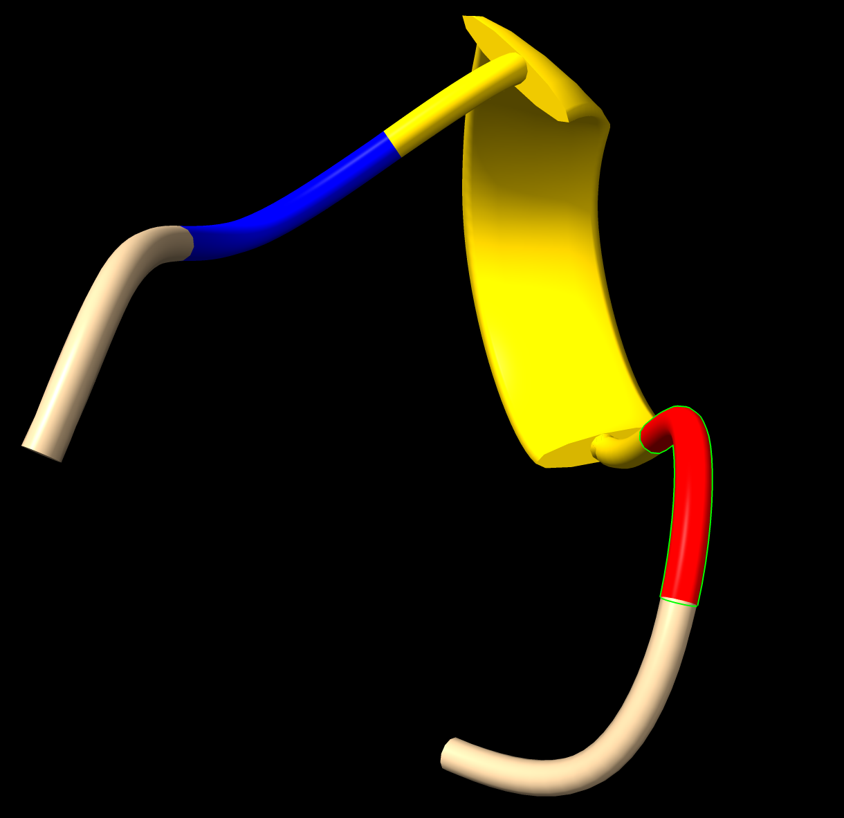
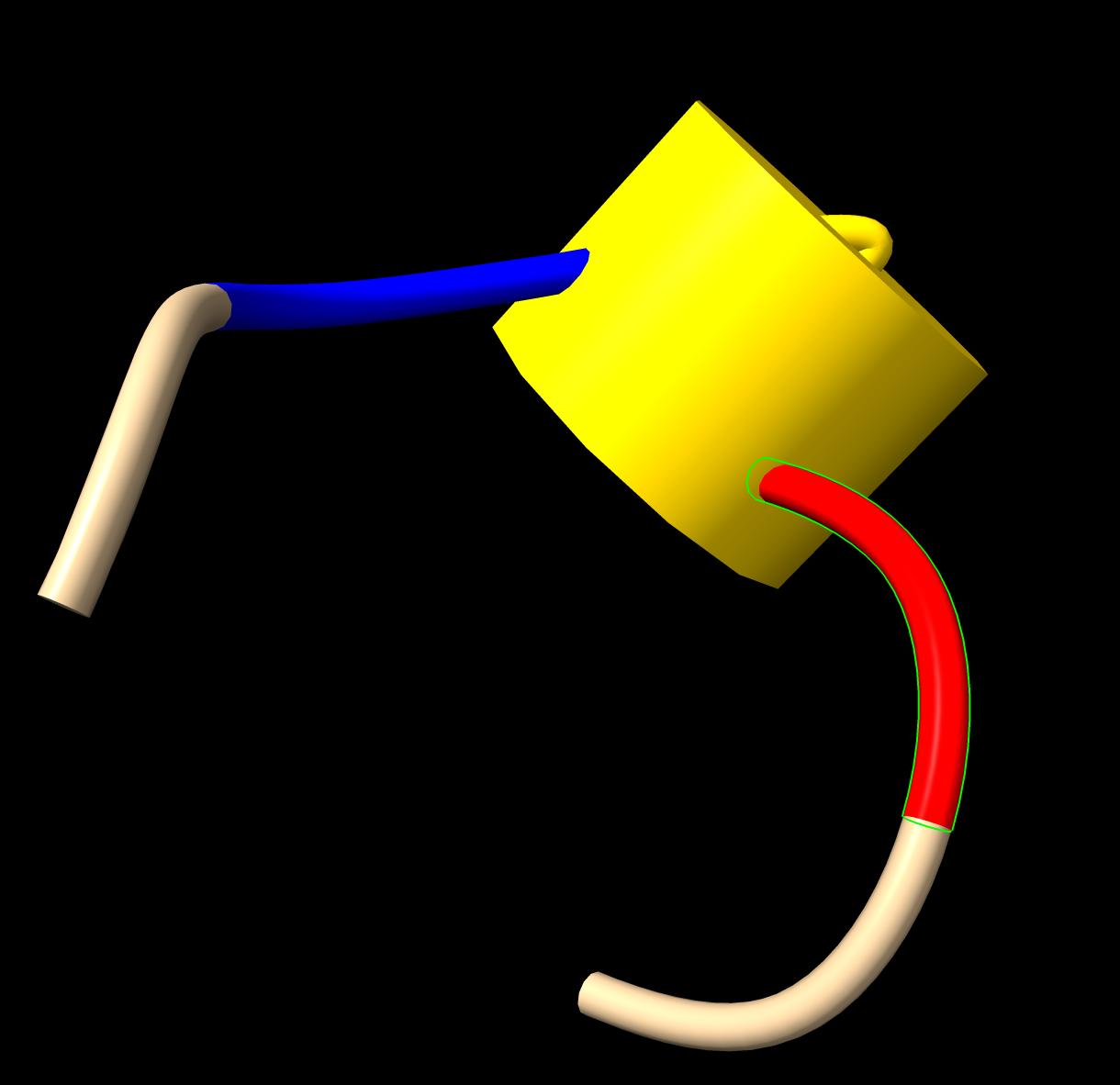
Looking at 1a0s, /Q:238,268,317,407 the first 3 tube helices look reasonable in current ChimeraX but the 3-residue helix residues :407-409 is a bit ugly in how the coli joins the cylinder, as shown in attached image 1a0s_407_tube.png and 1a0s_407_ribbon.png. Although it looks bad with the coil piercing the side of the cylinder instead of the end, it is geometrically essentially correct. By correct I mean the cylinder is correctly oriented so that the 3 CA atoms traverse a righthand helix around the cylinder with about correct pitch. By comparison in Chimera 1.14 the ribbon display is completely wrong with a 180 degree twist in the middle, and the pipes and planks cylinder is oriented completely wrong with the first and third CA essentially lying on the tube axis.
The reason this 3-residue helix looks especially bad is because the coil residues on both ends have CA atoms placed almost opposite where a continuation of the helix would place them.
Another factor important to understand with tube helix depiction is that the adjoining coil is forced to join to the center of the cylinder end cap. That is aesthetically nice in many cases, but completely wrong geometrically given that the end helix residue has its CA atom on the surface of the cylinder one cylinder radius distant from the end center connection point. So the depiction forces a connection to a physically incorrect position. Sometimes the adjoining coil CA is positioned to make this look preposterous. But this is not a problem with the cylinder orieintation, and is instead a consequence of trying to connect the coil to a point not on the helix CA backbone.
In summary, looking at just this one 1a0s 407 case (which occurs in many structures -- maybe 1 in 10 helix tubes), I think the depiction is correct if somewhat ugly with the cylinder in a near optimal position.
If I have misunderstood the problem or you have an idea of how to redefine the connection points to make it aesthetically more pleasing, then reopen the ticket.
by , 6 years ago
| Attachment: | 1a0s_407_ribbon.png added |
|---|
by , 6 years ago
| Attachment: | 1a0s_407_tube.png added |
|---|
comment:16 by , 6 years ago
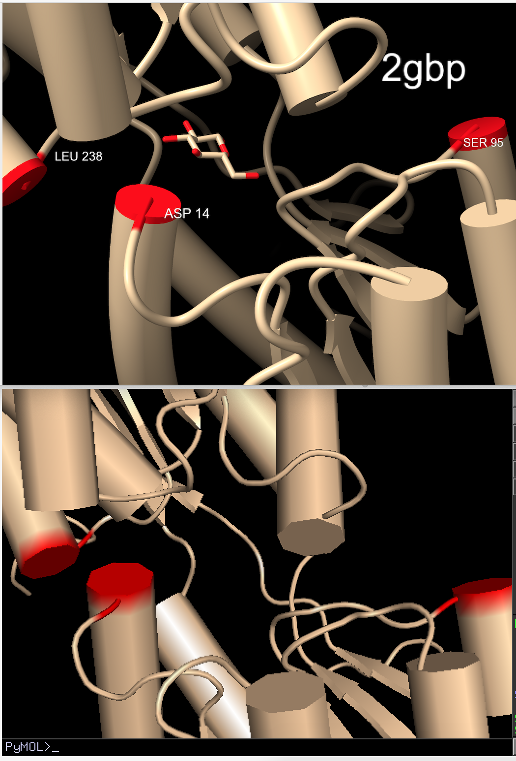
I just meant they were very ugly, without passing judgment on geometric correctness.  I was wondering if the loop segment could be forced to come out of the end at a nicer-looking angle, but that is probably incompatible with the mandate to pass through CA positions.

I was thinking they looked better in Pymol generally, but I see the angle is no better.  However, a small improvement in Pymol is that the extra bits beyond the end of the cylinder are sawed off so that the "wrong" end doesn't protrude.  See attached image with labels indicating structure and residue number: top panel is Chimera, bottom is Pymol.  Ignore the chunkiness of the Pymol cylinders, they can be made smoother but I didn't bother.

comment:17 by , 6 years ago
Thanks for showing what PyMol does with cylinder helices. From your image it appears the PyMol does not connect to the center of the cylinder end ever. Instead I bet it connects to the terminal CA at the end of the helix. So it always shows the coil entering the side of the cylinder. When I was working on ribbons I was surprised that our coils try to connect to the center of the end cap, and thought connecting to the terminal CA was more geometrically correct. But I did not want to change it since I was only working on optimization. Maybe the aesthetics of connecting to the center of the end cap are better? What do you think?
follow-up: 16 comment:18 by , 6 years ago
I think it's better to stick with the CA position. My only suggestion after looking at Pymol, now that I see that the entry angles are the same, was to saw off the wrong end of the coil segment where it would protrude from the cylinder end (exactly as in Pymol).
comment:19 by , 6 years ago
However, that little tweak is not more important than the other things we have on our dockets, so I'm OK with leaving ticket closed.
follow-up: 17 comment:20 by , 6 years ago
I don't think you understand how PyMol is connecting coil to cylinder.  It does not appear to be connecting the coil to the center of the end cap and not sawing off anything.  It is connecting most likely to the alpha helix CA which may always be just inside the cylinder in the PyMol implementation.  It would open a can of worms to change our tube helices to that style of connection.  Probably the CA does not lie inside our cylinders all the time.  And the aesthetics are very visibly different when the coil always enters from the side.

If you think it is worth pursuing that other style of depiction we can try in the future when there is time, but I would expect it to take several days just to see if it can be made to look good, as I expect multiple rounds of tweeks.  It isn't important enough to take several days now.
follow-up: 18 comment:21 by , 6 years ago
I didn't say it was connecting to the center. To me, the Pymol loop paths look exactly the same as in Chimera. The difference is that Chimera shows bits of the wrong end of the loop that protrude from the cylinder rather than cutting it off right where it joins. I am not suggesting any change in the geometric calculation of the loop path or the cylinder position.
follow-up: 19 comment:22 by , 6 years ago
In your PyMol vs ChimeraX image comparison the coil loop paths are not the same. Look at the two cylinders in the bottom right of the images where ChimeraX connects directly to the center of the end cap without intersecting the side of the cylinder and PyMol connects to the side of the cylinder.
follow-up: 20 comment:23 by , 6 years ago
I don't think the request here is to change the ChimeraX loop path in any way. The request is that if the loop path is so heavily kinked that it completely re-enters the cylinder, erase the part the precedes the re-entry.
follow-up: 22 comment:25 by , 6 years ago
It could be pretty easy to move the attachment end point at the center of the cylinder end-cap inside the cylinder along the axis by half a coil radius. Then if the coil approaches that point from within the cylinder it won't poke out of the cap.
by , 6 years ago
| Attachment: | 1a0s_407_mesh.png added |
|---|
comment:26 by , 6 years ago
| Resolution: | not a bug |
|---|---|
| Status: | closed → reopened |
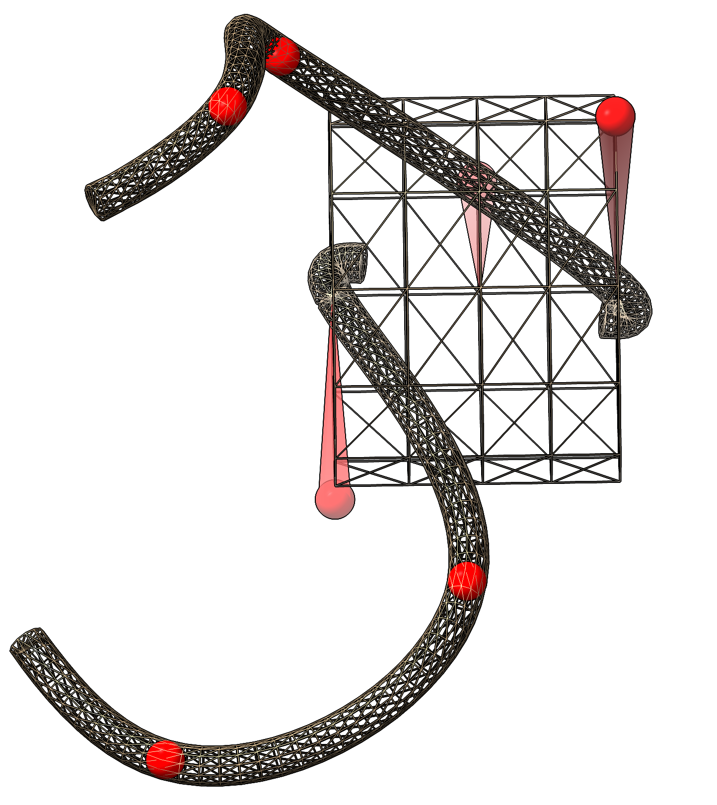
I've attached an image 1a0s_407_ mesh.png that shows the exact way ChimeraX is connecting the coil to the helix cylinder. The red balls are CA positions. It shows that the end of helix CA is exactly in the plane of the end cap at the edge of the cylinder. That CA projects onto the cylinder axis exactly at the center of the cylinder end cap and the coil is made to go through that point.
As suggested previously the coil could instead me made to go through a point inset by one coil radius along the axis which could fix the ugly appearance that is the subject of this ticket.
comment:27 by , 6 years ago
Would it be equally feasible to instead make the cylinder (well, tube) one coil radius longer on each end? Conceptually, would like to keep the cartoon going exactly through CA positions, a hard-won improvement relative to Chimera.
follow-up: 25 comment:28 by , 6 years ago
Another approach would be to make the cylinder longer extending by about 1/4 of a residue-residue spacing in the cylinder at each end. The actual extension needed to hide the coil popping out of the end cap is not clear because the coil in its approach to the end cap center makes a smooth spline that heads for the next interior projected CA along the cylinder axis. So the coil approaches the cap center from the outside and how far it swerves outside will depend on geometry. But probably some heuristic value of the extension could be chosen that handles most cases.
comment:29 by , 6 years ago
Ok I extended the helix tubes by 0.3 times the final two CA spacing along the helix axis. This greatly reduces the coils poking out from the inside of the cylinder. But it is not perfect. Specifically I see in 1mkj long curved helices that the final two CA atoms are sometimes spaced very close. Selecting the end helix residue shows only a sliver of the tube selected. Since the extension is a fraction of the final CA-CA distance at the helix end it doesn't extend at all. That raised the question of how the CA-CA distance along the helix axis could be near zero. That appears to be because the curve of the helix tube is far from correct, so the tube isn't parallel the actual helix near the end. Helices 1mkj 106-119 and also 336-349 are examples where the tube is very curved by the ribbon shows the helix as quite straight, and this leads to tight spacing of CA at the ends of the helices. This is a separate tube bug and I will make a separate ticket.
I could use a different rule for how long the helix tube extensions should be beyond the terminal helix CA. Instead of looking at the spacing of the final two CA I could take the average CA spacing along the entire helix. But maybe the problem will just go away if the tube curves are fixed.
I could add a cartoon style parameter to set the parameter controlling how long the tube extensions are (currently 0.3 times final CA-CA spacing). This would allow a user to tweak it if needed when making a figure to improve appearance.
comment:30 by , 6 years ago
I changed the helix tube extensions so their length is 0.3 times the average residue length in the helix instead of using the end residue length which was sometimes very short.
follow-up: 27 comment:31 by , 6 years ago
| Resolution: | → fixed |
|---|---|
| Status: | reopened → closed |
Fixed.
Coil junctions with tube helix look much better with the extended tube.
Wrong helix tube curve is described in new ticket #3012.
I think your observation about the problem being with shorter helices is correct. The way we currently compute the helical axis is by finding the principal axis from the CA coordinates. This works if the helix length is "sufficiently" greater than the helix width, but that is not true in this case (three-residue helices). There is another way to approximate the helical axis from four coordinates, but not three. Is it acceptable that cylinder representation can only be used for helices that are four residue or longer? (We currently already disallow 2-residue helices.)