Opened 7 years ago
Last modified 7 years ago
#2036 assigned enhancement
Clip command specifying initial plane position
| Reported by: | Owned by: | Tom Goddard | |
|---|---|---|---|
| Priority: | normal | Milestone: | |
| Component: | Graphics | Version: | |
| Keywords: | Cc: | Elaine Meng, Greg Couch | |
| Blocked By: | Blocking: | ||
| Notify when closed: | Platform: | all | |
| Project: | ChimeraX |
Description
The following bug report has been submitted:
Platform:        Darwin-18.6.0-x86_64-i386-64bit
ChimeraX Version: 0.91 (2019-06-08)
Description
Hi,

In the documentation for clip, it states:

"The offsets are relative to the position reference point, if given. Otherwise, offsets are relative to the current positions of the planes, or (if a plane is newly activated) the center of the bounding box of displayed models."

I don't quite understand the rationale for this last part. Whether the plane is newly activated or not, I would expect "clip near" or "clip far" to adjust the position of the plane, rather than clip in the middle of the box - it feels inconsistent. It maybe makes sense for "clip front/back", where the aim might often be to use the clip plane to cut the molecule in half (e.g. for visualizing a cavity), but for "clip near/far" I think it would be better if "clip near 1" always adjusted the near clip plane by 1 Å, rather than always except when the plane is newly activated.

Cheers
Oli

Log:
> camera ortho

> cofr centerOfView

> volume voxelLimit 100000 showPlane false limitVoxelCount false
voxelLimitForOpen 10000

> alias crosshairs_on log text crosshairs_on: diaplays crosshairs at center of
rotation and places cofr at center of view; cofr centerofview showpivot 5,0.2

> alias crosshairs_off cofr centerofview showpivot false

> alias cootmode volume style mesh step 1 squaremesh false meshlighting true
twosidedlighting false capfaces false; surface cap false; size stickradius
0.05; ~rib; color gold target a; color byhet; lighting flat; lighting
depthcuestart 0.2 depthcueend 0.7; set silhouettes false; set subdivision 1;
crosshairs_on; color #3333851effff target s; style stick; set bgcolor black

> alias cootmode_white volume style mesh step 1 squaremesh false meshlighting
true twosidedlighting false capfaces false; surface cap false; size
stickradius 0.05; ~rib; color orange target a; color byhet; lighting flat;
lighting depthcuestart 0.2 depthcueend 0.7; set silhouettes false; set
subdivision 1; crosshairs_on; color #00000000cccc target s; style stick; set
bgcolor white

> alias carve surface zone #* nearatoms sel distance $1 maxcomponents 1

> alias uncarve surface unzone #*

> alias focus view cofr false

> alias saturation_down color modify $1 saturation - 10

> alias saturation_up color modify $1 saturation + 10

> alias lightness_up color modify $1 lightness + 5

> alias lightness_down color modify $1 lightness - 5

> alias hue_up color modify $1 hue + 5

> alias hue_down color modify $1 hue - 5

UCSF ChimeraX version: 0.91 (2019-06-08)
© 2016-2019 Regents of the University of California. All rights reserved.
How to cite UCSF ChimeraX

> open 1bl8 format mmCIF fromDatabase pdb

1bl8 title:
Potassium channel (KCSA) from streptomyces lividans [more info...]

Chain information for 1bl8 #1
---
Chain | Description
A B C D | protein (potassium channel protein)


> crosshairs_on

crosshairs_on: diaplays crosshairs at center of rotation and places cofr at
center of view

> toolshed show "Side View"

Missing "near" keyword's argument

lightness_down

Missing or invalid first argument: Expected a text string

lightness_down

Missing or invalid first argument: Expected a text string

lightness_down

Missing or invalid first argument: Expected a text string

lightness_down

Missing or invalid first argument: Expected a text string

lightness_down

Missing or invalid first argument: Expected a text string

lightness_down

Missing or invalid first argument: Expected a text string

> clip off

Expected a keyword

Unknown command: symclip 10

> clip near 1

> clip near 1

> clip far 1

clip far plane is in front of near plane

incomplete quoted text

> view

> clip near 1

> clip far 1

clip far plane is in front of near plane

> view


OpenGL version: 4.1 ATI-2.9.26
OpenGL renderer: AMD Radeon Pro 580 OpenGL Engine
OpenGL vendor: ATI Technologies Inc.
Attachments (2)
Change History (9)
comment:1 by , 7 years ago
| Cc: | added |
|---|---|
| Component: | Unassigned → Graphics |
| Owner: | set to |
| Platform: | → all |
| Project: | → ChimeraX |
| Status: | new → assigned |
| Summary: | ChimeraX bug report submission → Clip command inconsistency |
| Type: | defect → enhancement |
comment:2 by , 7 years ago
follow-up: 3 comment:3 by , 7 years ago
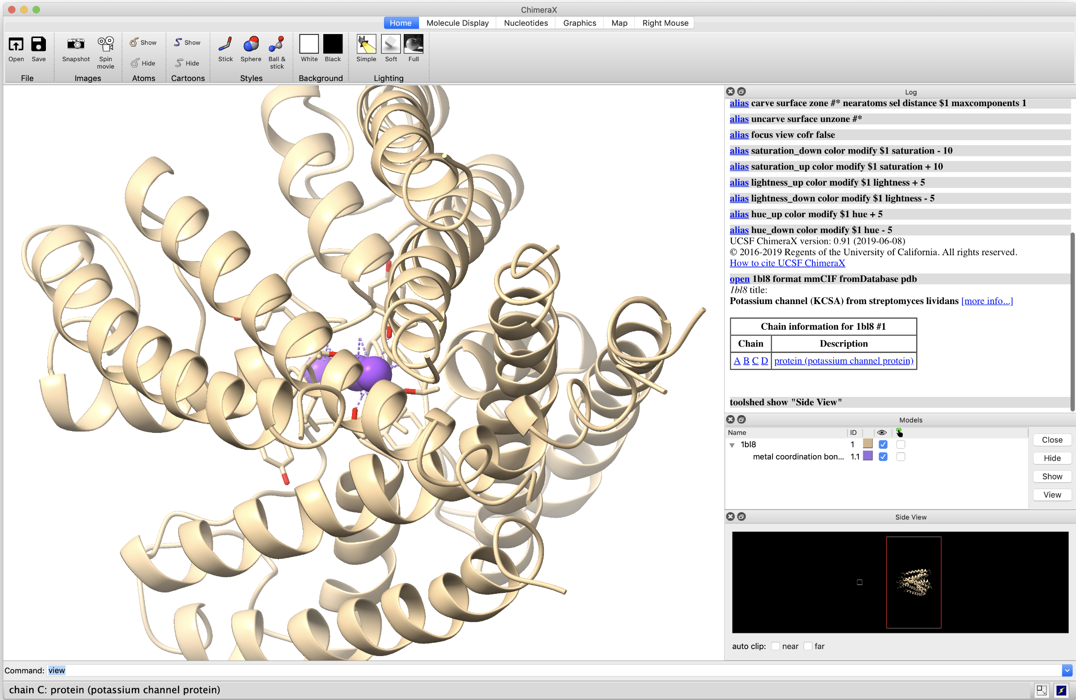
I guess one of the issues is that there is no visual distinction in Side View between what you call the bounding box (when no clip planes have been actively placed) and what one sees when the near/far clip planes have been altered (e.g. by dragging the bounding box).

Perhaps a visual indicator (maybe a colored line on the appropriate edge of the bounding box?) would help here?

But yes, I was thinking that it might make more sense to initialize the near/far clip planes at the edges of the bounding box, rather than in the center of the model, because it seemed more consistent with there behavior in any other conference, but maybe I am thinking about it wrong.

Cheers
Oli
follow-up: 4 comment:4 by , 7 years ago
Here is a mockup.

The idea would be that when the user grabs one side of the bounding box, it transforms into a line of a different color (representing the clip plane), and likewise when the user unchecks one of the auto-clip boxes.

As a user, I find it a little counterintuitive that when “auto-clip” is on, this actually means there are no clip planes defined. This might be one way of making that clearer visually.

It would be also be nice to have a button to rotate the representation in Side View around z (exists in Chimera via the “side” dropdown).

In the future (I realize this is probably way down the list) it would be useful to be able to display and adjust the depth cueing start/end planes in Side View. I think this would be a convenient, quick way to make adjustments to the lighting in a scene.

Cheers
Oli

comment:5 by , 7 years ago
| Cc: | added |
|---|
I don't use side view so I was confused when you were talking about "auto-clip". That is wording in the side view window that is confusing -- I'll make a ticket to change that. Clipping is off or it is on. Side view should be changed to say "Clip" and checkboxes will be on when clip planes are enabled -- like in Chimera 1. The lines shown on the side view drawing are depictions used to enable and move clip planes by dragging them.
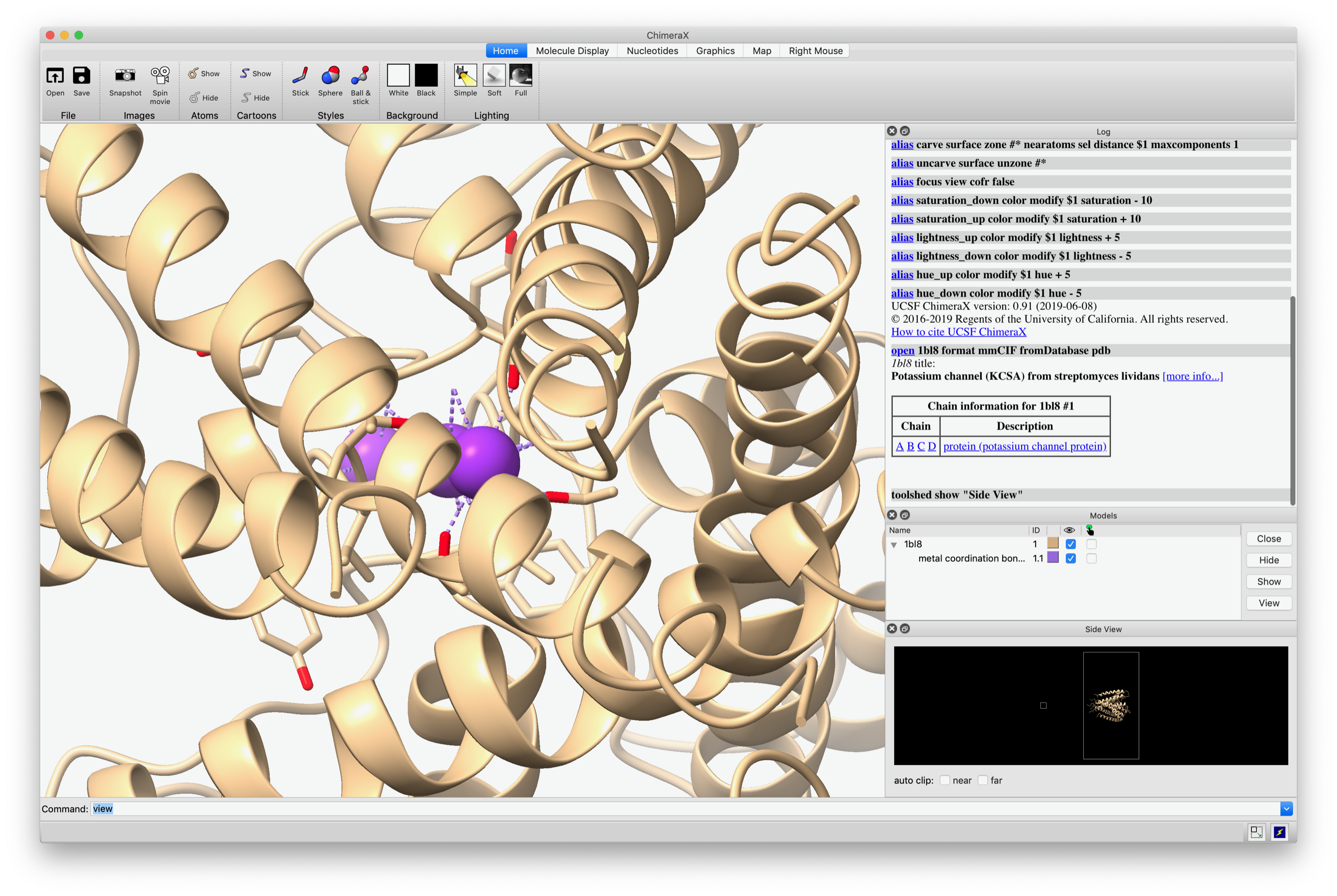
comment:6 by , 7 years ago
Thanks Tom that would be good. The red lines I added because I felt like they made it clearer - what I was suggesting is that a line should be present (and draggable) when the corresponding clip plane is on, and otherwise just show the bounding box like in the attached screenshot. It would perhaps be better to only allow adjustment of the clip plane when the corresponding clip plane box is checked, to avoid confusion between the bounding box and clip planes.

Cheers
Oli

follow-up: 6 comment:7 by , 7 years ago
| Summary: | Clip command inconsistency → Clip command specifying initial plane position |
|---|
I think this ticket is based on a misconception that clip planes are always on, that probably came from the "auto-clip" terminology in side view and perhaps experience with other software. I've made a ticket #2041 to use more consistent terminology to avoid this confusion.
The clip command behavior is still pretty bizarre in that the initial position is specified relative to bounding box center while subsequent positioning is done relative to the current plane position. I think making initial position relative to the front/back of the bounding box while being more consistent works especially poorly because ChimeraX does not have accurate positions for the front of and back of the model.
If the clip plane is a new clip plane then it didn't exist before, so relative to its current position does not make sense. Maybe you mean that if there is no clip plane the positioning should be relative to a some point in front of the models based on the displayed bounding box. That could possibly work, but the bounding box is not precise (it may be computed in a rotated coordinate frame) and the front-most point may be off by a large distance. So that is not a reference point that will be easy to use. You might move a newly created clip plane 20 Angstroms toward the model and still it does not clip the model.