#15899 closed defect (fixed)
Hidden vertices in GLB output, and GLB nodes not centered at (0,0,0)
| Reported by: | Owned by: | Tom Goddard | |
|---|---|---|---|
| Priority: | normal | Milestone: | |
| Component: | Input/Output | Version: | |
| Keywords: | Cc: | Elaine Meng, phil.cruz@… | |
| Blocked By: | Blocking: | ||
| Notify when closed: | Platform: | all | |
| Project: | ChimeraX |
Description
The following bug report has been submitted:
Platform: Windows-10-10.0.22631
ChimeraX Version: 1.7.1 (2024-01-23 01:58:08 UTC)
Description
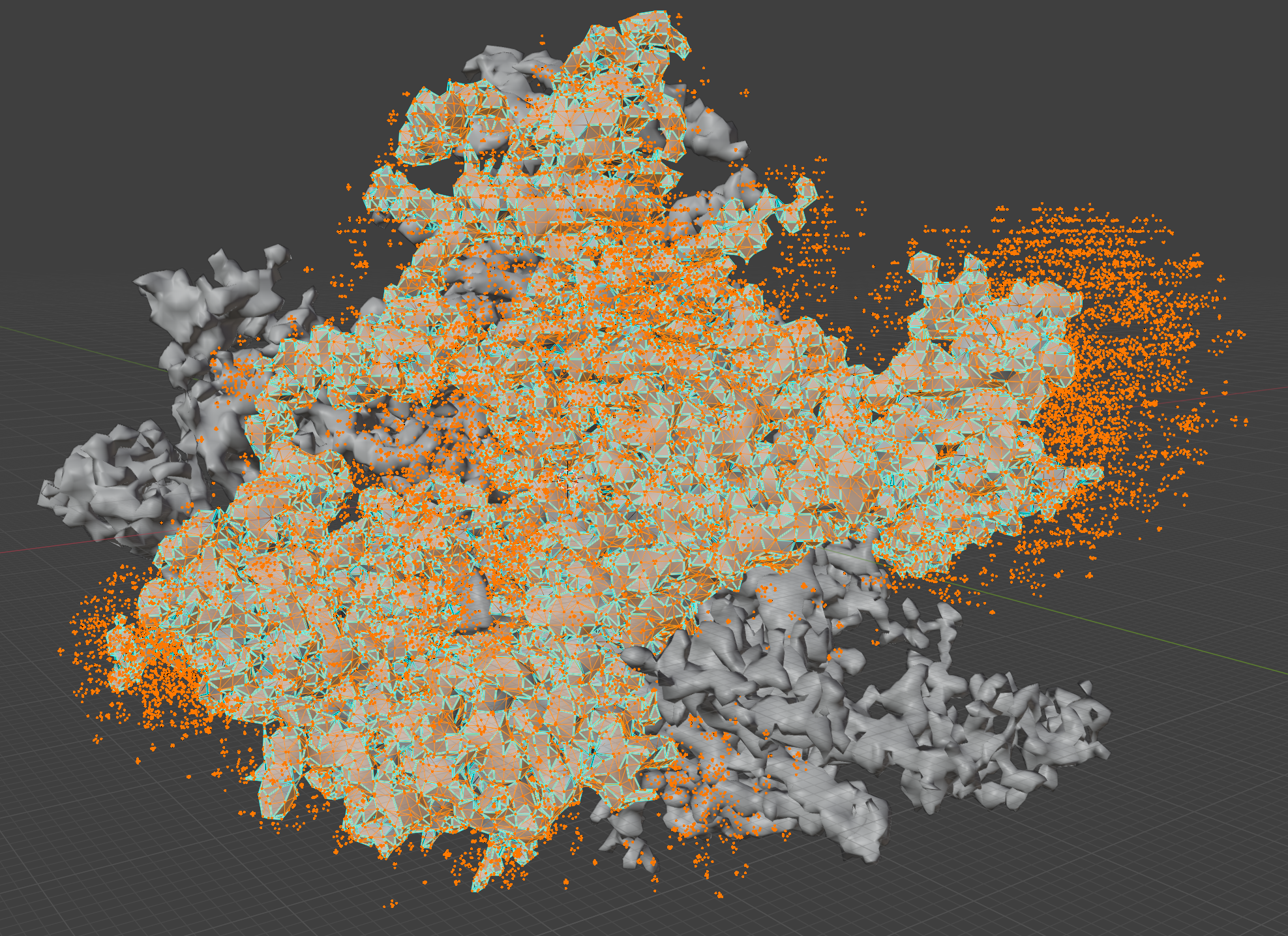
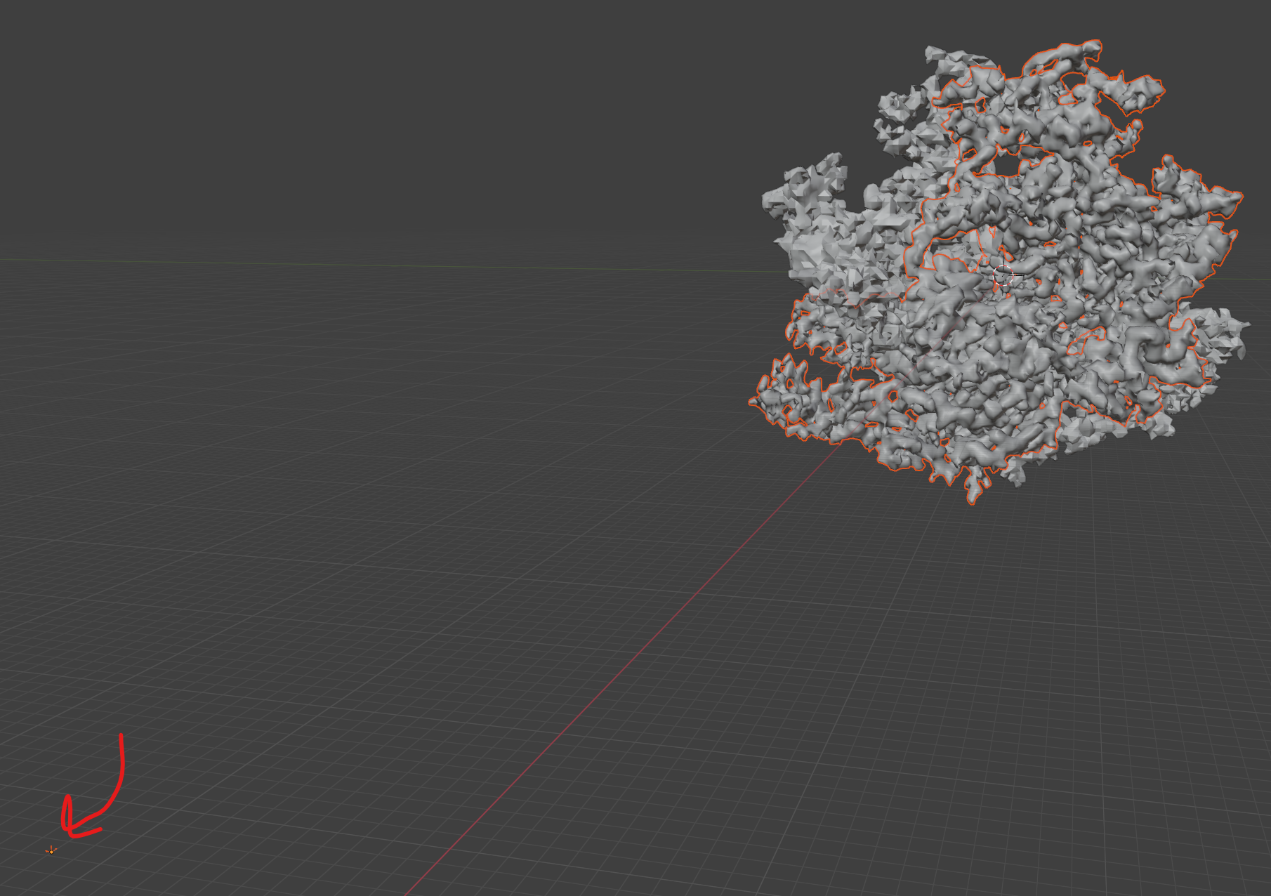
opem emdb: 36702, run the radial NIH 3D preset, then export as a GLB and a WRL. The GLB is fine, but the WRL has a cloud of vertices around it. Seems like an issue with the exporter? The output is also in a different orientation and position relative to the glb output and I'd expect them to be the same. I attached an image of a Blender scene with the WRL file highlighted with it's cloud of vertices, then the glb is underneath it.
Log:
Startup Messages
---
note | available bundle cache has not been initialized yet
UCSF ChimeraX version: 1.7.1 (2024-01-23)
© 2016-2023 Regents of the University of California. All rights reserved.
How to cite UCSF ChimeraX
> open emd:36702
No such database 'emd'
> open emdb:36702
Summary of feedback from opening 36702 fetched from emdb
---
notes | Fetching compressed map 36702 from
ftp://ftp.ebi.ac.uk/pub/databases/emdb/structures/EMD-36702/map/emd_36702.map.gz
Fetching map header 36702 from
ftp://ftp.ebi.ac.uk/pub/databases/emdb/structures/EMD-36702/header/emd-36702.xml
Opened emdb 36702 as #1, grid size 260,260,260, pixel 1.41, shown at level
0.029, step 2, values float32, fit PDB 8jxi
> preset nih3d "volume radial"
Using preset: NIH3D / Volume Radial
Could not access metadata for EMDB entry 36702
Enclosed volume for surface (#1.1) = 6.386e+04
Enclosed volume for surface (#1.1) = 5.566e+04
Changed 0 atom radii, 0 bond radii, 0 pseudobond radii
Changed 0 pseudobond dashes
Color 'marine' is opaque: rgb(0%, 50%, 100%) hex: #0080ff
Color 'forest' is opaque: rgb(13.3%, 54.5%, 13.3%) hex: #228b22
Color 'tangerine' is opaque: rgb(95.3%, 51.8%, 0%) hex: #f38400
Color 'grape' is opaque: rgb(64.3%, 0%, 86.7%) hex: #a400dd
Color 'nih_blue' is opaque: rgb(12.5%, 33.3%, 54.1%) hex: #20558a
Color 'jmol_carbon' is opaque: gray(56.5%) hex: #909090
Color 'bond_purple' is opaque: rgb(57.6%, 43.9%, 85.9%) hex: #9370db
Color 'struts_grey' is opaque: gray(48%) hex: #7a7a7a
Color 'carbon_grey' is opaque: gray(22.2%) hex: #393939
Using preset: Initial Styles / Original Look
Preset implemented in Python; no expansion to individual ChimeraX commands
available.
Preset expands to these ChimeraX commands:
~struts
~hbonds
close ##name='3D-printable missing structure'
show ##name='missing structure' models
size atomRadius default stickRadius 0.2 pseudobondRadius 0.2
style dashes 7
graphics quality bondSides default
graphics quality pseudobondSides 10
cartoon style sides 12
graphics bgcolor white
color name marine 0,50,100
color name forest 13.3,54.5,13.3
color name tangerine 95.3,51.8,0
color name grape 64.3,0,86.7
color name nih_blue 12.5,33.3,54.1
color name jmol_carbon 56.5,56.5,56.5
color name bond_purple 57.6,43.9,85.9
color name struts_grey 48,48,48
color name carbon_grey 22.2,22.2,22.2
surface close
preset 'initial styles' 'original look'
volume #1 region all style surface step 1 limitVoxelCount false
wait 1
surface dust #1.1 size 1 metric 'size rank'
color radial #1 palette red:yellow:green:cyan:blue center #1
> save C:/Users/brownekm/test_emd.glb
> save C:/Users/brownekm/Downloads/test.wrl
OpenGL version: 3.3.0 NVIDIA 555.99
OpenGL renderer: NVIDIA GeForce RTX 2080 Ti/PCIe/SSE2
OpenGL vendor: NVIDIA Corporation
Python: 3.11.2
Locale: en_US.cp1252
Qt version: PyQt6 6.3.1, Qt 6.3.1
Qt runtime version: 6.3.2
Qt platform: windows
Manufacturer: HP
Model: HP Z4 G4 Workstation
OS: Microsoft Windows 11 Enterprise (Build 22631)
Memory: 137,220,087,808
MaxProcessMemory: 137,438,953,344
CPU: 20 Intel(R) Core(TM) i9-10900X CPU @ 3.70GHz
OSLanguage: en-US
Installed Packages:
alabaster: 0.7.16
appdirs: 1.4.4
asttokens: 2.4.1
Babel: 2.14.0
backcall: 0.2.0
beautifulsoup4: 4.11.2
blockdiag: 3.0.0
blosc2: 2.0.0
build: 0.10.0
certifi: 2023.11.17
cftime: 1.6.3
charset-normalizer: 3.3.2
ChimeraX-AddCharge: 1.5.13
ChimeraX-AddH: 2.2.5
ChimeraX-AlignmentAlgorithms: 2.0.1
ChimeraX-AlignmentHdrs: 3.4.1
ChimeraX-AlignmentMatrices: 2.1
ChimeraX-Alignments: 2.12.2
ChimeraX-AlphaFold: 1.0
ChimeraX-AltlocExplorer: 1.1.1
ChimeraX-AmberInfo: 1.0
ChimeraX-Arrays: 1.1
ChimeraX-Atomic: 1.49.1
ChimeraX-AtomicLibrary: 12.1.5
ChimeraX-AtomSearch: 2.0.1
ChimeraX-AxesPlanes: 2.3.2
ChimeraX-BasicActions: 1.1.2
ChimeraX-BILD: 1.0
ChimeraX-BlastProtein: 2.1.2
ChimeraX-BondRot: 2.0.4
ChimeraX-BugReporter: 1.0.1
ChimeraX-BuildStructure: 2.10.5
ChimeraX-Bumps: 1.0
ChimeraX-BundleBuilder: 1.2.2
ChimeraX-ButtonPanel: 1.0.1
ChimeraX-CageBuilder: 1.0.1
ChimeraX-CellPack: 1.0
ChimeraX-Centroids: 1.3.2
ChimeraX-ChangeChains: 1.1
ChimeraX-CheckWaters: 1.3.2
ChimeraX-ChemGroup: 2.0.1
ChimeraX-Clashes: 2.2.4
ChimeraX-ColorActions: 1.0.3
ChimeraX-ColorGlobe: 1.0
ChimeraX-ColorKey: 1.5.5
ChimeraX-CommandLine: 1.2.5
ChimeraX-ConnectStructure: 2.0.1
ChimeraX-Contacts: 1.0.1
ChimeraX-Core: 1.7.1
ChimeraX-CoreFormats: 1.2
ChimeraX-coulombic: 1.4.2
ChimeraX-Crosslinks: 1.0
ChimeraX-Crystal: 1.0
ChimeraX-CrystalContacts: 1.0.1
ChimeraX-DataFormats: 1.2.3
ChimeraX-Dicom: 1.2
ChimeraX-DistMonitor: 1.4
ChimeraX-DockPrep: 1.1.3
ChimeraX-Dssp: 2.0
ChimeraX-EMDB-SFF: 1.0
ChimeraX-ESMFold: 1.0
ChimeraX-FileHistory: 1.0.1
ChimeraX-FunctionKey: 1.0.1
ChimeraX-Geometry: 1.3
ChimeraX-gltf: 1.0
ChimeraX-Graphics: 1.1.1
ChimeraX-Hbonds: 2.4
ChimeraX-Help: 1.2.2
ChimeraX-HKCage: 1.3
ChimeraX-IHM: 1.1
ChimeraX-ImageFormats: 1.2
ChimeraX-IMOD: 1.0
ChimeraX-IO: 1.0.1
ChimeraX-ItemsInspection: 1.0.1
ChimeraX-IUPAC: 1.0
ChimeraX-Label: 1.1.8
ChimeraX-ListInfo: 1.2.2
ChimeraX-Log: 1.1.6
ChimeraX-LookingGlass: 1.1
ChimeraX-Maestro: 1.9.1
ChimeraX-Map: 1.1.4
ChimeraX-MapData: 2.0
ChimeraX-MapEraser: 1.0.1
ChimeraX-MapFilter: 2.0.1
ChimeraX-MapFit: 2.0
ChimeraX-MapSeries: 2.1.1
ChimeraX-Markers: 1.0.1
ChimeraX-Mask: 1.0.2
ChimeraX-MatchMaker: 2.1.2
ChimeraX-MCopy: 1.0
ChimeraX-MDcrds: 2.6.1
ChimeraX-MedicalToolbar: 1.0.2
ChimeraX-Meeting: 1.0.1
ChimeraX-MLP: 1.1.1
ChimeraX-mmCIF: 2.12.1
ChimeraX-MMTF: 2.2
ChimeraX-Modeller: 1.5.14
ChimeraX-ModelPanel: 1.4
ChimeraX-ModelSeries: 1.0.1
ChimeraX-Mol2: 2.0.3
ChimeraX-Mole: 1.0
ChimeraX-Morph: 1.0.2
ChimeraX-MouseModes: 1.2
ChimeraX-Movie: 1.0
ChimeraX-Neuron: 1.0
ChimeraX-Nifti: 1.1
ChimeraX-NIHPresets: 1.1.18
ChimeraX-NRRD: 1.1
ChimeraX-Nucleotides: 2.0.3
ChimeraX-OpenCommand: 1.13.1
ChimeraX-PDB: 2.7.3
ChimeraX-PDBBio: 1.0.1
ChimeraX-PDBLibrary: 1.0.4
ChimeraX-PDBMatrices: 1.0
ChimeraX-PickBlobs: 1.0.1
ChimeraX-Positions: 1.0
ChimeraX-PresetMgr: 1.1
ChimeraX-PubChem: 2.1
ChimeraX-ReadPbonds: 1.0.1
ChimeraX-Registration: 1.1.2
ChimeraX-RemoteControl: 1.0
ChimeraX-RenderByAttr: 1.1
ChimeraX-RenumberResidues: 1.1
ChimeraX-ResidueFit: 1.0.1
ChimeraX-RestServer: 1.2
ChimeraX-RNALayout: 1.0
ChimeraX-RotamerLibMgr: 4.0
ChimeraX-RotamerLibsDunbrack: 2.0
ChimeraX-RotamerLibsDynameomics: 2.0
ChimeraX-RotamerLibsRichardson: 2.0
ChimeraX-SaveCommand: 1.5.1
ChimeraX-SchemeMgr: 1.0
ChimeraX-SDF: 2.0.2
ChimeraX-Segger: 1.0
ChimeraX-Segment: 1.0.1
ChimeraX-SelInspector: 1.0
ChimeraX-SeqView: 2.11
ChimeraX-Shape: 1.0.1
ChimeraX-Shell: 1.0.1
ChimeraX-Shortcuts: 1.1.1
ChimeraX-ShowSequences: 1.0.2
ChimeraX-SideView: 1.0.1
ChimeraX-Smiles: 2.1.2
ChimeraX-SmoothLines: 1.0
ChimeraX-SpaceNavigator: 1.0
ChimeraX-StdCommands: 1.12.4
ChimeraX-STL: 1.0.1
ChimeraX-Storm: 1.0
ChimeraX-StructMeasure: 1.1.2
ChimeraX-Struts: 1.0.1
ChimeraX-Surface: 1.0.1
ChimeraX-SwapAA: 2.0.1
ChimeraX-SwapRes: 2.2.2
ChimeraX-TapeMeasure: 1.0
ChimeraX-TaskManager: 1.0
ChimeraX-Test: 1.0
ChimeraX-Toolbar: 1.1.2
ChimeraX-ToolshedUtils: 1.2.4
ChimeraX-Topography: 1.0
ChimeraX-ToQuest: 1.0
ChimeraX-Tug: 1.0.1
ChimeraX-UI: 1.33.3
ChimeraX-uniprot: 2.3
ChimeraX-UnitCell: 1.0.1
ChimeraX-ViewDockX: 1.3.2
ChimeraX-VIPERdb: 1.0
ChimeraX-Vive: 1.1
ChimeraX-VolumeMenu: 1.0.1
ChimeraX-vrml: 1.0
ChimeraX-VTK: 1.0
ChimeraX-WavefrontOBJ: 1.0
ChimeraX-WebCam: 1.0.2
ChimeraX-WebServices: 1.1.3
ChimeraX-Zone: 1.0.1
colorama: 0.4.6
comm: 0.2.1
comtypes: 1.1.14
contourpy: 1.2.0
cxservices: 1.2.2
cycler: 0.12.1
Cython: 0.29.33
debugpy: 1.8.0
decorator: 5.1.1
docutils: 0.19
executing: 2.0.1
filelock: 3.9.0
fonttools: 4.47.2
funcparserlib: 2.0.0a0
glfw: 2.6.4
grako: 3.16.5
h5py: 3.10.0
html2text: 2020.1.16
idna: 3.6
ihm: 0.38
imagecodecs: 2023.9.18
imagesize: 1.4.1
ipykernel: 6.23.2
ipython: 8.14.0
ipython-genutils: 0.2.0
ipywidgets: 8.1.1
jedi: 0.18.2
Jinja2: 3.1.2
jupyter-client: 8.2.0
jupyter-core: 5.7.1
jupyterlab-widgets: 3.0.9
kiwisolver: 1.4.5
line-profiler: 4.0.2
lxml: 4.9.2
lz4: 4.3.2
MarkupSafe: 2.1.4
matplotlib: 3.7.2
matplotlib-inline: 0.1.6
msgpack: 1.0.4
nest-asyncio: 1.6.0
netCDF4: 1.6.2
networkx: 3.1
nibabel: 5.0.1
nptyping: 2.5.0
numexpr: 2.8.8
numpy: 1.25.1
openvr: 1.23.701
packaging: 23.2
ParmEd: 3.4.3
parso: 0.8.3
pep517: 0.13.0
pickleshare: 0.7.5
pillow: 10.2.0
pip: 23.0
pkginfo: 1.9.6
platformdirs: 4.1.0
prompt-toolkit: 3.0.43
psutil: 5.9.5
pure-eval: 0.2.2
py-cpuinfo: 9.0.0
pycollada: 0.7.2
pydicom: 2.3.0
Pygments: 2.16.1
pynrrd: 1.0.0
PyOpenGL: 3.1.7
PyOpenGL-accelerate: 3.1.7
pyopenxr: 1.0.2801
pyparsing: 3.0.9
pyproject-hooks: 1.0.0
PyQt6-commercial: 6.3.1
PyQt6-Qt6: 6.3.2
PyQt6-sip: 13.4.0
PyQt6-WebEngine-commercial: 6.3.1
PyQt6-WebEngine-Qt6: 6.3.2
python-dateutil: 2.8.2
pytz: 2023.3.post1
pywin32: 305
pyzmq: 25.1.2
qtconsole: 5.4.3
QtPy: 2.4.1
RandomWords: 0.4.0
requests: 2.31.0
scipy: 1.11.1
setuptools: 67.4.0
sfftk-rw: 0.7.3
six: 1.16.0
snowballstemmer: 2.2.0
sortedcontainers: 2.4.0
soupsieve: 2.5
sphinx: 6.1.3
sphinx-autodoc-typehints: 1.22
sphinxcontrib-applehelp: 1.0.8
sphinxcontrib-blockdiag: 3.0.0
sphinxcontrib-devhelp: 1.0.6
sphinxcontrib-htmlhelp: 2.0.5
sphinxcontrib-jsmath: 1.0.1
sphinxcontrib-qthelp: 1.0.7
sphinxcontrib-serializinghtml: 1.1.10
stack-data: 0.6.3
superqt: 0.5.0
tables: 3.8.0
tcia-utils: 1.5.1
tifffile: 2023.7.18
tinyarray: 1.2.4
tomli: 2.0.1
tornado: 6.4
traitlets: 5.9.0
typing-extensions: 4.9.0
tzdata: 2023.4
urllib3: 2.1.0
wcwidth: 0.2.13
webcolors: 1.12
wheel: 0.38.4
wheel-filename: 1.4.1
widgetsnbextension: 4.0.9
WMI: 1.5.1
File attachment: output.png
Attachments (13)
Change History (42)
by , 23 months ago
| Attachment: | output.png added |
|---|
comment:1 by , 23 months ago
| Cc: | added |
|---|---|
| Component: | Unassigned → Input/Output |
| Owner: | set to |
| Platform: | → all |
| Project: | → ChimeraX |
| Status: | new → assigned |
| Summary: | ChimeraX bug report submission → WRL vs. GLB output |
comment:2 by , 23 months ago
The dots shown in Blender around the surface are a Blender issue -- those dots should not be shown. For example, using a VRML web viewer does not show the dots
Maybe Blender is showing them just to indicate that the file does contain extra vertices although the file does not render them. The reason there are extra vertices is because the volume radial preset did a hide dust which hid part of the surface. But that does not delete the dust part of the surface and that is why the vertices (but not the triangles) for the dust appear in the VRML file.
Saving a .glb file by default centers the output at 0,0,0 while saving VRML does not do that centering. That is one reason they will not align. But it appears the rotation is different in your image. But in the web vrml viewer I mention above the orientation exactly matches the .glb and the original map file. Maybe you rotated the scene before you saved the .wrl file and that is why it is showing a different orientation.
If you want the VRML output to center I can probably add an option for that. If you need the unshown dust vertices to actually be deleted from the file, I could probably add some option to do that too.
comment:3 by , 23 months ago
My previous comment that rotating the view before saving the VRML was wrong -- that would not effect the orientation in the VRML. The VRML and GLTF ignore the camera view direction in ChimeraX and just output using ChimeraX scene coordinates. So I don't understand how the VRML could be rotated relative to the GLTF, and they do not appear rotated relative to one another in my test using an external web vrml viewer.
comment:4 by , 23 months ago
Tom:
I've added a script on my end to remove the vertex "cloud" from the wrl files for NIH 3D purposes. They don't render unless you switch to edit mode which highlights all vertices. It seems to me like they should be removed as having all of these vertices wouldn't be something I'd expect and it impacts the bounding box and pivot point sometimes. I had talked to Phil about this before he left for Africa and he thought it looked like a bug, so I'd lean toward it should be fixed for wrl exports in general if possible.
I exported the wrl and glb files directly from ChimeraX in the example I showed you then loaded them into blender without any modification. I also looked at an stl output direct from chimeraX and all are loading in different orientations. The only reason this is an issue is that we are using wrl, glb, and stl outputs, and when I render them in Blender the renders come out at different angles and I couldn't figure out exactly what the position/rotation difference was. If they can all be centered such that the pivot point and position is the same for all exports it would really make it easier to figure out a correction for the rotation. In general, having the anchor point in the middle of the object and having the position at 0,0,0 makes the objects more usable if it can be done.
K
comment:5 by , 23 months ago
I did:
open emdb:36702
picked the volume radial preset from the NIH 3D presets
Saved as wrl
Saved as glb
I think the issue is the glb output. Looking at when I import the file:
[cid:image001.png@01DB02DF.0C0C5920]
The imported file has location and rotation values assigned to it:
[cid:image002.png@01DB02DF.0C0C5920]
and the pivot is way out in the middle of nowhere (arrow) so it's hard to match the rotation to the wrl output.
I also checked in Babylon:
[cid:image003.png@01DB02DF.0C0C5920]
And again the positions are set and the anchor is in the middle of nowhere so the rotation isn't around the center of the object. The rotation is 0,0,0 in Babylon, which may have to do with Blender switching things into it's own z-up space.
The wrl imports like this:
[cid:image004.png@01DB02DF.0C0C5920]
The pivot is in the middle of the object (which is good) and it has rotation on the x and z axes. I've seen wrl exporters apply these rotations in pymeshlab as well and they aren't a big deal if the objects have the same anchor point.
I also looked at 3dviewer.net which can open both formats and it gives me the same orientation for the glb and wrl which is different from the view that Babylon and Blender give. The viewer rotates the camera and not the object, so it's hard to tell where the anchor point is, but it is possible this viewer is recalculating the object center when it imports (The NIH 3D viewer does this to account for these issues from ChimeraX models and some user-inputs). I can't say for sure as this viewer doesn't have as sophisticated controls as the Babylon viewer.
I think it's likely that the issue stems from the glb not having it's axis correctly centered on the geometry. I can fix both the axis and the rotation using Blender, but I think it would be better for ChimeraX to do this. The current glb exports are hard to manipulate and position in a scene because they move relative to that axis center which can be very far from the object itself. I've had to account for this in the NIH 3D viewer by recalculating everything when I import the objects into the viewer, but this really shouldn't be necessary and may be an barrier to those without the knowledge to fix the issue.
Hopefully that provides a bit more information,
K


comment:6 by , 23 months ago
Hi Kristen,
I went on a fact-finding expedition and here is what I found. Both the ChimeraX .glb output and the .wrl output by default center the exported scene so the center of the bounding box is at 0,0,0. Here is the ChimeraX documentation for saving GLTF that shows "center True" is the default
https://www.cgl.ucsf.edu/chimerax/docs/user/commands/save.html#gltf
And here is the ChimeraX documentation for saving VRML that also sets "center True" is the default
https://www.cgl.ucsf.edu/chimerax/docs/user/commands/save.html#gltf
I checked the code for both of these to see how it is done. For VRML the vertex coordinates of the meshes are shifted. For GLTF a top-level centering transform shifts the entire scene to place the bounding box center at 0,0,0.
I checked whether that is working just now with your example EMDB 36702 in BabylonJS sandbox and it appears to be working correctly. You see in my image (emdb_36702_babylonjs.png attached) the axes are correctly centered at the middle of the surface. I believe in your babylonjs image you have clicked the "centering" node instead of the "root" node and that is why in your image the axes are not centered on the surface. When you select the centering node you also see the (-160,-104,-165) offset because the centering transformation that shifts that point to 0 in the root scene is not being applied. So you have to use the root scene of the GLTF to get the correct positioning.
Also the orientation of the surface when opened in BabylonJS exactly matches what is seen in ChimeraX.
So my test in BabylonJS suggests the ChimeraX GLTF is correctly written. BabylonJS seems to stick exactly to the GLTF standard in my experience with it.
I have not tested in Blender, and who knows what Blender does with it.
For the ChimeraX VRML output I don't have any decent VRML viewer like BabylonJS so I'm not sure how to test that it produces the correct center at 0,0,0 and the correct orientation. But if I understand your statement it seems that it is working ok, except for the extra hidden vertices.
ChimeraX output in GLTF, VRML or STL does not rotate the models or set any rotations, so the view when opening in a viewer should be exactly the initial unrotated view in ChimeraX. Or possibly the viewer will decide not to look down the z-axis so you might get an initial view down a different axis.
Both GLTF and VRML output from ChimeraX include hidden vertices that viewers should not display. But I agree with you that eliminating those would avoid tripping up software that tries to use the models and make the files a little smaller. I think it is not too hard to renumber the vertices and rebuild the triangle lists to remove unused vertices, for instance those hidden by "hide dust" in the exported files. I try to do that.
For the centering problem we need to really focus on a precise case to look at. You tried so many different viewers and .glb and .wrl and it is just too hard to try to straighten out all those problems at once. I suspect almost all the problems are with those viewer programs. For instance, I don't think .glb has any notion of an "anchor point". That is something viewer software defines, and possibly defines in a way you don't like in some cases. I agree we want the ChimeraX and NIH 3D models to work well in viewer programs but since different viewers may do different things for the centering there is probably no way to get them all to work well because the problems are in the viewers. But if we look at a specific viewer (e.g. Blender) and specific file (e.g. emdb 36702 .glb) we can try to understand why the viewer is setting a rotation that does not match what BabylonJS uses ((0,0,0) in the root scene).
Tom
by , 23 months ago
| Attachment: | emdb_36702_babylonjs.png added |
|---|
BabylonJS sandbox view of EMDB 36702 with NIH radial preset, showing centering of the scene correctly located at (0,0,0).
comment:7 by , 23 months ago
Tom:
The "root" node in Babylon is generated by Babylon.js to transform glTF's coordinate space into Babylon.js coordinate space and is not representative of the file itself. Blender has no "root" node because it isn't technically part of the file. I tried in C4D as well, and it loads the GLB by placing it inside of a "scene" object that is centered, then the "centering" object is buried in it.
So there is indeed some inconsistency as to how all of these packages are handling the import of glTF files. Some are placing it inside another object and Blender is not. I can fix the pivot on the centering object in Blender for NIH 3D, but others using glTF from ChimeraX in Blender may need some documentation showing them how to reset the origin to use the files. I'm not sure what the VR packages like EnDuvo do with these on import, but EnDuvo also didn't support vertex color so I'm not sure they are using the chimeraX models are being used there with any frequency by the VizLab.
I'd say lets put a pin in it until next meeting as Phil is ultimately the decider and I do have a work-around for NIH 3D. I think we have a good sense of what is causing the inconsistency between viewers and how glTF is handling anchor points, so that helps us squeak forward.
I think getting rid of the cloud of vertices is still a good way to go just to create a more compact file containing only useful geometry.
Thanks!
K
comment:8 by , 23 months ago
Hi Kristen,
I don't understand the centering problem with .glb. The first part of the .glb file is text and here it is for your example
JSON{"asset": {"version": "2.0", "generator": "UCSF ChimeraX 1.9.dev202407250342"}, "scenes": [{"nodes": [2]}], "nodes": [{"name": "emdb 36702", "children": [1]}, {"name": "surface", "mesh": 0}, {"name": "centering", "children": [0], "matrix": [1, 0, 0, 0, 0, 1, 0, 0, 0, 0, 1, 0, -160.12539672851562, -104.11528015136719, -165.6245880126953, 1]}], "meshes": [{"primitives": [{"attributes": {"POSITION": 0, "NORMAL": 1, "COLOR_0": 2}, "indices": 3, "mode": 4, "material": 0}]}], "accessors": [{"count": 82762, "type": "VEC3", "componentType": 5126, "min": [99.15726470947266, 45.51429748535156, 102.22604370117188], "max": [239.1072998046875, 161.9818878173828, 229.0090789794922], "bufferView": 0}, {"count": 82762, "type": "VEC3", "componentType": 5126, "bufferView": 1}, {"count": 82762, "type": "VEC4", "componentType": 5123, "normalized": true, "bufferView": 2}, {"count": 333852, "type": "SCALAR", "componentType": 5125, "bufferView": 3}], "bufferViews": [{"byteLength": 993144, "byteOffset": 0, "buffer": 0, "target": 34962}, {"byteLength": 993144, "byteOffset": 993144, "buffer": 0, "target": 34962}, {"byteLength": 662096, "byteOffset": 1986288, "buffer": 0, "target": 34962}, {"byteLength": 1335408, "byteOffset": 2648384, "buffer": 0, "target": 34963}], "buffers": [{"byteLength": 3983792}], "materials": [{"pbrMetallicRoughness": {"baseColorFactor": [1.0, 1.0, 1.0, 1.0], "metallicFactor": 0, "roughnessFactor": 1}}]}
There is the part that defines the "centering" node and gives a "matrix" which does the centering. From what you say that is not working correctly, although it appears to me to be working correctly in BabylonJS. I think a worthwhile test would be to make the output the .glb from ChimeraX without the centering (command "save test.glb center false") and compare the centering in Blender or C4D or any of the software where you think the centering is not working. See if the files with centering and without centering give the same center as if the software is ignoring the centering matrix, or if they give different results. If the results are different is the one without centering correct? Maybe the sign of the translation in the matrix is opposite what it should be.
The reason I say BabylonJS appears to show the centering working is that the "default camera" node "target" shows as -9,-.037,-.01 which is approximately 0,0,0 (the size of the surface is about 300). The reason it is not exactly 0,0,0 is I believe because ChimeraX is including the hidden vertices when computing the center of bounding box while BabylonJS is probably computing it correctly to center its camera and so they are slightly different.
I will compare centered versus not centered in BabylonJS and if you could do it in the other software we might figure out if some of the software is just ignoring the matrix that is supposed to do the centering. If it is ignoring the matrix then we may need to use some other technique.
I will also try to remove the unused vertices, although that is not related to the far off centering issue.
Tom
comment:9 by , 23 months ago
I tried a .glb from ChimeraX without centering in BabylonJS and as expected it put the coordinate origin far away from the map, attached image emdb_36702_no_centering_babylonjs.png.
So my tests in BabylonJS suggest it understands the matrix that does centering and it does the right thing putting the origin at the middle of the surface.
My best guess is the other software like Blender and C4D are ignoring the matrix.
by , 23 months ago
| Attachment: | emdb_36702_no_centering_babylonjs.png added |
|---|
Shows EMDB 36702 .glb exported from ChimeraX with "center false" in BabylonJS with the origin of the root scene as expected far from the center of the surface.
comment:10 by , 23 months ago
I think the object is centered at 0,0,0 of world space, and when the objects are brought into to most of these viewers, the object is added to a root object that has both a local and world space origin at 0,0,0. But when that root object isn't added (like in Blender), the glTF object has an origin in "local space" and has translation values to move the geometry to the world origin of 0,0,0. When rotating an object, it will by default use the "local space" origin which is in the middle of nowhere.
To fix it, I had to move the geometry back to the local space 0,0,0 (essentially removing those transforms), reset all of the transforms (essentially setting everything to 0,0,0) , then reset the pivot to the center of mass. From there I move the whole thing back to the world 0,0,0 and since the pivot is centered, the local origin is also at world 0,0,0 and behaves as expected. This is my standard procedure when importing a ChimeraX mesh. These commands likely have more going on under the hood, but those are the operators that I'm using to predictably orient the models.
For surfaces, I set the rotation values to -90, 0, -180 for wrl and -90,0,0 for glb to line up with the stl files (I picked an arbitrary one to line up to).
Once those steps were done all objects rotate and translate around the center of mass and are all rendered identically from Blender.
k
comment:11 by , 23 months ago
World space and local space are Blender concepts, not GLTF. In GLTF there is a notion of a scene and it contains nodes. In the ChimeraX case with centering the scene has one node called "centering" and that node has a transformation matrix that makes it so (0,0,0) in the coordinates of the scene is at the center of the surface bounding box. It appears that Blender is ignoring the transformation of the centering node. It doesn't make sense to me, it seems that Blender is ignoring what the GLTF file says. It either simply does not use the transformation at all, or it sees the transformation at the top level and decides to ignore it. This would not surprise me. Conformance to 3D standards by various software is abysmal. But it is difficult for me to work around software that is not following what is in the GLTF file.
You've told me the details of how you "fix" the problem in Blender, but since I don't use Blender that doesn't clarify to me why Blender chooses to ignore the transformation given in the centering node. What I want to know is whether Blender is simply ignoring the transformation given in the file. One way to ascertain that is to compare what Blender does with the ChimeraX .glb written without centering to what Blender does with the file written with centering. If those look the same in Blender I would conclude Blender just ignored the centering transformation. That is why I asked you to test that. If we determine it is ignoring the centering transformation then we know we won't be able to get Blender to center ChimeraX .glb using that method due to a limitation of Blender and we can try to figure out how to do centering so that Blender works properly. The usual way of fixing this, is that if software does not support the features of the GLTF file format then you can't use those features. So for instance you have to do centering my moving every vertex instead of by applying a top level transformation. That can get complex because there are vertices in lots of places and some may have other instancing transformations that change the shift needed for centering.
comment:12 by , 23 months ago
The target of the camera in Babylon in the Sandbox calculates a bounding box around the object (you can see it with the square icon that is in the same line as "scene" in the debugger), then the camera locks to the center of that. I can see the transforms are applied in Blender and in Babylon on the centering object. Babylon expects users to not necessarily anchor their models correctly, so they calculate a bounding box using the mesh object and use that to target the camera. I've done this myself in NIH 3D because without it, Babylon has the same issues as Blender does with these files.
I can't see the JSON in my files, but the transform looks like it's moving the object in local space, but this isn't really what is needed. The bounding box is defined by the min/max values, and the center of that box should be at 0,0,0. If it isn't, then the amount that it is off from 0,0,0 is the amount that all of the vertices need to be moved. ChatGPT says this is accomplished by changing the buffer data associated with the POSITION attribute. "The buffer reference by bufferView 0 needs to be updated to reflect the new vertex positions".
This is essentially what I'm doing in Blender. Remove that transform, then move the whole object to 0,0,0 in world space.
K
comment:13 by , 23 months ago
BabylonJS reports the default camera target as close to 0,0,0 with the ChimeraX .glb centering. In otherwords BabylonJS computed the bounding box and used the centering transformation and so it gets the desired center near 0,0,0. It should be exactly 0,0,0 but the discrepancy is a ChimeraX problem. If I open the uncentered ChimeraX .glb in BabylonJS then the default camera target center is (-160, -104, -165). So it seems the centering does what it is supposed to in BabylonJS. So I am trying to understand what you mean by "Babylon has the same issues as Blender does with these files".
comment:14 by , 23 months ago
Tom:
I did some reading and the "world origin" is equivalent to the "local origin" of the root object prior to any transformations. Transformations are relative to the "world origin".
According to the json:
"scenes": [{"nodes": [2]}],
"nodes": [
{"name": "emdb 36702", "children": [1]},
{"name": "surface", "mesh": 0},
{"name": "centering", "children": [0], "matrix": [1, 0, 0, 0, 0, 1, 0, 0, 0, 0, 1, 0, -160.12539672851562, -104.11528015136719, -165.6245880126953, 1]}]
The node of index = 2 is the "root" node for the scene. This indicates that "centering" is the root node of the scene as defined by the gltf. Any root node that is subsequently added by Babylon.JS, C4D etc is the result of those programs writing in a root node that doesn't exist in the file itself.
Based on the transform matrix, the "centering" object local origin has been moved to -160, -104, -165 in world space. But visual inspection shows that the child nodes are not also at -160, -104, -165 which suggests that the local origin of centering is not at the center of mass of the mesh object. This is what I see in Blender and in Babylon when manipulating center. The local origin should be at the center of mass of the geometry, and the local origin should be at 0,0,0 in world space.
The Babylon sandbox calculates a bounding box that wraps the geometry and ignores where the local space origin is (there's no geometry there). Then it points the camera at the center of that box. So in the "centered" version, that points at 0,0,0 because the object geometry is at a world position of 0,0,0. When uncentered it points at -160,-104,-165 because it's pointing at the center of the geometry which is now sitting where the local origin was in the "centered" version. When I was writing the NIH 3D viewer, I had to start from scratch, and at first the ChimeraX models would often have uncentered anchor points and rotate oddly. I had to snatch some code from the sandbox to have the root object rotate like it does in the sandbox. So Babylon.sandbox manipulates the object for optimal viewing/centering of the object and isn't representative of the "true" gltf object.
Blender doesn't do this, it maintains the original scene structure because the glb is already suitable for the Blender coordinate system. So Blender would technically be representing the "True" gltf file so far as I can tell.
K
comment:15 by , 23 months ago
I made ChimeraX GLTF and VRML export remove unused vertices. This fix will be in the ChimeraX daily build dated September 10, 2024 and newer.
This should fix the cloud of vertices you saw with the VRML models of volumes that used hide dust when viewed in edit mode in Blender. Also it fixes the small deviation from 0,0,0 in the BabylonJS viewer for the default camera target position which was caused by BabylonJS including those unused vertices in the bounding box calculation.
comment:16 by , 23 months ago
Hi Kristen,
The BabylonJS root node has a 180 degree rotation about y and flips z -> -z. I guess that is because the BabylonJS coordinate system does not match the standard GLTF coordinate system (x axis horizontal pointing right, y axis vertical pointing up, z axis pointing out of the screen toward you to make right handed coordinate system). So BabylonJS adds a root node in order to convert the GLTF coordinate system to the BabylonJS coordinate system. The ChimeraX coordinate system is the same as GLTF. The BabylonJS root node seems to work correctly since the orientation of the scene shown in BabylonJS matches the orientation shown in ChimeraX. From what I read online Blender has the y-axis pointing into the screen and the z-axis pointing vertically in the plane of the screen, so it is rotated 90 degrees about x relative to the GLTF and ChimeraX coordinate systems.
https://en.wikibooks.org/wiki/Blender_3D:_Noob_to_Pro/Understanding_Coordinates
In the .glb output from ChimeraX the centering is to put (0,0,0) at the center of the bounding box. Why do you say the origin should be at the "center of mass"? What do you mean by mass? Each triangle has weight proportional to area? Or the enclosed volume of uniform mass? Do you really want a center of mass origin instead of center of bounding box?
Everything I see in BabylonJS with the ChimeraX .glb looks correct. BabylonJS puts the camera target at (0,0,0) now that I got rid of the unused vertices that were throwing BabylonJS box calculation off. That is exactly what centering is intended to do. The centering node matrix shifts the children objects by (-160, -104, -165). That is the amount of shift, not the origin. The center of the bounding box of the surface without the centering node is (160, 104, 165) (without the negative signs) and the centering matrix shifts in the negative direction so that the surface center has coordinates 0,0,0 in the centering node coordinate system.
So everything looks exactly as it should be in BabylonJS, the ChimeraX .glb appears correct and is being interpreted correctly by BabylongJS (except it mishandles unused vertices including them in the bounding box calculation). I'm embarrassed to keep saying this, I don't understand what problem you think the ChimeraX centered .glb has. I don't see any center of rotation issues in BabylonJS with this file. Perhaps you mean that if you strip away the centering node and work with the child surface node then it is not centered at 0,0,0. Of course that would be true. Or maybe you mean that BabylonJS is working fine but Blender is not. I have not looked into what Blender is doing (beyond seeing that its standard coordinate system supposedly does not match GLTF or ChimeraX).
Maybe you can explain the exact steps you do in BabylonJS or Blender (open file, rotate using this exact method, rotation is not around expected center...) that is not behaving as you expect it to.
Tom
comment:17 by , 23 months ago
Tom:
Sorry this is so confounding based on how the viewers are handling things.
GLTF World and Local Space
While glTF doesn't explicitly have something called "world space" or "local space", functionally it does. The position of the root object (the highest index scene object) prior to any transformations is at a conceptual "world space" of 0,0,0. When you translate it, it will move the scene object relative to the "world space" along with its children. In this case, it is moving the "centering" node by -160,-104,-165. When this happens, it is moving the "centering" node "local space origin" by those values. In this case, this happens to move the geometry that is a child of that scene object to a world space of 0,0,0 because the geometry is offset from the "local space" origin by 160, 104, 165.
"Local Space" would be defined as where the JSON max/min properties define the bounding box for a particular bufferView. Each scene object has its own bufferView. The center of that bounding box would be the "local space" for the scene object.
So for the rest of this I'm going to use the following definitions based on the above:
World Space Origin (0,0,0 in world space)
Local Space Origin (the center of the bounding box for the geometry)
Note - the Local Space Origin is represented by the "Axis" crosshairs, so when I talk about the "Axis" I'm talking about the "Local Space Origin".
Geometry - Only the geometry that is contained in the glTF file
The Root Node - This is a Babylon Sandbox construct
What I said earlier about the bounding box was a misunderstanding, it was relating to how the camera frames the object, not how the root node is created. So I apologize for confusion there.
As described above, the root object of a glTF file is the scene object in the JSON file with the highest index (in this case the "centering" node).
In Babylon Sandbox, for any dropped file it will create a "root" node and load the glTF scene as a child of that object. "root" is always at the Babylon World Origin. It is not part of the glTF file or format, it is a construct of the Babylon Sandbox to make the objects that are dropped in have a standard manipulation point. If the geometry in the glTF happens to be located at the world origin and you rotate the "root", it will rotate all of it's child objects around the world origin.
This is the origin of the "root" object created by Babylon (note I rotated to the TOP view so you can see the grid):
[cid:image006.png@01DB0432.E4F15A20]
But this is artificial, selecting the "centering" node shows you what the location of the origin for the glTF file, and it's at -160, -104, -165 which you can see here:
[cid:image007.png@01DB0432.E4F15A20]
This is also what I see in Blender which doesn't create an artificial root node. It won't make artificial corrections like Babylon Sandbox that would be an inconvenience to users that have purposefully built models this way. Blender shows the file as-is.
The Root Problem - The geometry AND the local origin for that geometry should both be at the world origin
With the centering node (Front view - this is the same as the Babylon and ChimeraX front view):
[cid:image003.png@01DB042B.8FF2A3F0]
You can see where the axis/local origin is in the lower left (at -160,-104,-165) with the geometry at the world origin which is the center of the blue and red cross-hairs in the grid (they are very thin, but hopefully you can see them).
Without centering:
[cid:image004.png@01DB042B.8FF2A3F0]
The axis/local origin is at the world origin and the geometry has move relative to that point up to a position of 160, 104, 165 presumably.
So the "Centering" node translates the local origin and it's child nodes such that the geometry happens to land at the world origin, but the local origin is offset from the geometry.
What is Expected:
Below is the result of updating the object by removing the centering node and moving the geometry such that the bounding box is centered at the local origin (which is already at the world origin when you remove the centering node):
[cid:image005.png@01DB042C.4D049660]
This object will rotate and translate relative to the axis and center of the geometry which are both at 0,0,0.
Looking at the json, it doesn't have a translation, the min/max values describing the position of the bounding box have changed, as have the buffer byte length etc.
The json for this file is:
{
"asset":{
"generator":"Khronos glTF Blender I/O v4.2.57",
"version":"2.0"
},
"scene":0,
"scenes":[
{
"name":"Scene",
"nodes":[
1
]
}
],
"nodes":[
{
"mesh":0,
"name":"surface"
},
{
"children":[
0
],
"name":"emdb 36702"
}
],
"materials":[
{
"name":"Material_0",
"pbrMetallicRoughness":{
"metallicFactor":0
}
}
],
"meshes":[
{
"name":"Mesh_0",
"primitives":[
{
"attributes":{
"POSITION":0,
"NORMAL":1,
"COLOR_0":2
},
"indices":3,
"material":0
}
]
}
],
"accessors":[
{
"bufferView":0,
"componentType":5126,
"count":55044,
"max":[
68.07838439941406,
62.24816131591797,
52.70318603515625
],
"min":[
-53.857887268066406,
-53.48505401611328,
-63.383705139160156
],
"type":"VEC3"
},
{
"bufferView":1,
"componentType":5126,
"count":55044,
"type":"VEC3"
},
{
"bufferView":2,
"componentType":5126,
"count":55044,
"type":"VEC3"
},
{
"bufferView":3,
"componentType":5123,
"count":333852,
"type":"SCALAR"
}
],
"bufferViews":[
{
"buffer":0,
"byteLength":660528,
"byteOffset":0,
"target":34962
},
{
"buffer":0,
"byteLength":660528,
"byteOffset":660528,
"target":34962
},
{
"buffer":0,
"byteLength":660528,
"byteOffset":1321056,
"target":34962
},
{
"buffer":0,
"byteLength":667704,
"byteOffset":1981584,
"target":34963
}
],
"buffers":[
{
"byteLength":2649288,
"uri":"untitled.bin"
}
]
}
Why this is important:
When manipulating objects, especially rotating them, it is almost always relative to the local space origin. If you're trying to set up a scene with many objects scattered around, you don't want to rotate them relative to the center of the world. You want to rotate them around the local space origin, which you would generally expect to be at the center of the geometry (there are some exceptions to that). With this offset, you often can't even find the manipulator without zooming way out. Some software are adding a parent node as a convenience for this type of thing, some do not. But what Blender is doing is "correct" as far as I can see from the glTF JSON data and descriptions.
I'm making a fair assumption that many of those outputting glb files will use Blender as it is one of the few software packages that can natively import the format. It is also free so in standard use by the research community. So from a usability perspective, it also makes sense to use Blender as the "gold-standard".
Can/Should it be fixed by ChimeraX?
I don't know if this is possible for ChimeraX to accomplish, but this is how I would expect the glTF to be constructed such that the file will rotate/translate/scale around an axis centered on the geometry that is in world space at 0,0,0. You may also be able to do what Babylon does and drop in a parent node at 0,0,0 (this also works in Blender). The reason I don't love this solution is that it has the same issue as Babylon Sandbox. It isn't "fixing" the root problem, the geometry is still not centered on its local origin. It's just buried in a node structure that will need to be maintained for the file to be usuable.
That all being said, I have already made fixes to accommodate all issues in NIH 3D, so again this is up to Phil as to whether it is worth fixing for other purposes.
Hopefully that helps clarify,
K
PS. Blender indeed uses a bizarre z-up space that is common in manufacturing, but there are default import/export settings to account for this. There is no difference between a "front" view in Blender and "front" view in Babylon.


comment:18 by , 23 months ago
Hi Kristen,
Thanks for your immense patience explaining this to me! I think I get it now. Let me try explaining the way I understand it and if I have it right we can come up with a solution.
You have a scene in a GLTF file that is a tree of nodes. Each node can have a transformation matrix, for instance, in the current ChimeraX GLTF the top centering node has a translation so that the bounding box of the entire scene is centered at 0,0,0 in the world coordinates. Let's imagine my scene has two atomic models that are a ways apart from each other. I might want to rotate one of those two atomic models in the scene about its center. So in Blender I could click on its node and rotate it. But that works poorly now because Blender takes the pivot for rotation at 0,0,0 in the local coordinates of that node. That atomic model came from crystallography and its bounding box is far away from 0,0,0. So it ends up rotating around a point far from the center of the atomic model which is bad. It surprises me quite a bit that Blender and other 3D scene software would work that way. I would expect it to rotate not about 0,0,0 in the node local coordinates. I would expect it by default to rotate about the center of the bounding box of the node. Since it doesn't work that way the tree of nodes ideally should be created so that for every node its bounding box is centered at 0,0,0 in the local coordinates of that node. The node can then have a transformation on it that places the node in the correct position within its parent node. This is a restrictive constraint on how the transformations of all the nodes are set to maintain this property that every node has its geometry centered at 0,0,0 in the node's local coordinate system.
ChimeraX and molecular data in general is not restricted in that way. But I see that any node hierarchy can have its transformations replaced and vertex buffers shifted to have that property. Basically it amounts to going to the bottom of the tree where there are vertex buffers, shifting them to center them, and then undoing the shift using the transform in the node that references those buffers. And you just walk from the leaves of the tree up to the root modifying the transformations all the way to the top node doing the same trick, shift all the child nodes of a parent so the parent is centered at 0,0,0 and then reposition the parent using its transform so it maintains its original position in the scene. The end result is every node is centered at 0,0,0 in its local coordinates and the scene looks identical, you just juggled the positioning transformations between child nodes and parent nodes.
I've never had to work with a restrictive scene graph rule like this. But from what you say it is the norm that 3D graphics software like Blender and C4D rely on this assumption and if it is violated the user interface in those programs becomes very challenging to use.
If I understand the situation correctly I can see if I can do the transformation propagation from vertex buffers up the tree to make a more usable GLTF file. One casualty of that is that you lose the original crystallographic coordinates for say an x-ray atomic model node. The node no longer has those coordinates and you only know where it is in the overall scene. But for use of these GLTF files where knowing the original source data coordinates is not likely to be important, that is no loss.
Tom
comment:19 by , 23 months ago
That all sounds right!
There are reasons why we sometimes have the local axis in a different place then the object itself. For example, if I had a box and I wanted the bottom of the box to align with the ground plane, I would shift the anchor to be at the bottom of the box. Then I can set the "location" of the box to a y position of 0 and the box would perfectly sit on the ground. Another example would be if I want to radially distribute a model, like this example: [Solved: Mash radial radius not small ...]
I’d set the pivot to the middle of world space, then duplicate and rotate the object a bunch of times. There are tools that do this in different ways, but this is a valid approach. Since there are “reasons” why you might anchor things differently, Blender respects that when importing files and doesn’t make any assumptions. I think this makes sense as the pivots are more about “manipulating” objects in a scene, whereas Babylon is more concerned with inspecting the geometry, so it optimizes for that scenario.
These was a good exercise to understand the glTF format better, so I’m glad we had the discussion. I don’t think I realized that you think in the atomic space while I’m thinking about things in the 3D modeling space, so your explanation helps me understand where you are coming from better 😊
I agree that there is little expectation that someone would be deriving any atomic information from the glb files, but I should let Phil make the final call on this when he gets back.
K

comment:20 by , 23 months ago
Ok, I added a centerEachNode option to the save command for saving .glb default true. It makes each node in the output GLTF have bounding box centered at 0,0,0 in the local coordinates of that node.
I'm wondering if center of bounding box is the best choice. Maybe the mean vertex position with equally weighted vertices is a better definition of center for a node. I tested with a trimer and the bounding box center is not at the center of the trimer, but if the mean vertex position were used the center would be at the geometric center of the trimer. Which definition of the "center" of the node do you think is preferable? Both are easy to compute.
comment:21 by , 23 months ago
The new option is in tonight's ChimeraX builds (dated Sept 11, 2024 or newer).
comment:22 by , 23 months ago
I changed the centerEachNode option so it uses the average vertex position to define the center for a node rather than the center of the bounding box since this gives a more sensible center for symmetric objects.
comment:23 by , 23 months ago
| Cc: | added; removed |
|---|---|
| Resolution: | → fixed |
| Status: | assigned → closed |
| Summary: | WRL vs. GLB output → Hidden vertices in GLB output, and GLB nodes not centered at (0,0,0) |
Fixed.
Elaine could you document the new save gltf option centerEachNode (default true) which adjusts the transforms of the scene nodes in the GLTF file so that each node is centered at (0,0,0) in its local coordinate system. This does not change the position of any object in the scene but instead changes the tree of nodes (each node is an object like a molecule, a map, a ribbon) so that if the GLTF file is edited in Blender or other 3D software that software can easily manipulate individual tree nodes (e.g. rotate them) because the object for that node is centered at (0,0,0). This option is only of interest if you are concerned with inspecting or editing the GLTF node tree in other software. The center point for an object is defined as the average of all vertex positions present in the object.
This was an improvement for Kristen Browne of the NIAID. She thinks other users of the NIH 3D GLTF models may load them in 3D editors where the local centering will be useful. For users of NIH 3D who just want to 3D print a GLTF this option has no effect.
comment:24 by , 23 months ago
Kristen, ChimeraX VRML output only includes one node, a single IndexedFaceSet for everything in the ChimeraX scene. By default it is centered at (0,0,0) by shifting all the vertices. So the local origin problem that was seen with GLTF output does not happen in VRML. But also the VRML will not allow you to easily separate out individual scene objects since it does not use a tree of nodes. The VRML output could use a tree of nodes, but that is much more complex to produce.
comment:25 by , 23 months ago
The the local centering is a great feature, thank you!
The rotation issue isn't a major concern, as it's unlikely that other users will be importing multiple objects in different formats into the same scene. With the vertex cleanup and the local centering of the GLB, I can now reliably predict the rotation to align my renders in Blender, so everything seems ready to go! When the extra vertices were present and the local center was misaligned, it was difficult to pinpoint the problem. But now, it's an easy and predictable fix.
Thanks!
K
comment:26 by , 23 months ago
After I catch Phil up on everything next week, I think we'll want to enable this centering option in the NIH 3D workflows (if it isn't the default), but I don't want to make that call without informing Phil.
K
comment:28 by , 22 months ago
Tom:
I talked to Phil this morning and he agrees that preserving the atomic coordinates so far as GLB files is not important. He noted that he's seen the rotation issues I see in Blender when they used IQ3, so the changes we've discussed will improve the usability of the glb objects in other applications as well.
We think this could be released alongside the alphafold changes in NIH 3D should everything be ready.
Thanks for your efforts on this!
Kristen
Added by email2trac