Opened 2 years ago
Last modified 2 years ago
#15639 assigned enhancement
RFE: depth testing for volumes
| Reported by: | Zach Pearson | Owned by: | Zach Pearson |
|---|---|---|---|
| Priority: | moderate | Milestone: | |
| Component: | Graphics | Version: | |
| Keywords: | Cc: | Tom Goddard, Greg Couch | |
| Blocked By: | Blocking: | ||
| Notify when closed: | Platform: | all | |
| Project: | ChimeraX |
Description
Currently it looks like opaque models are always drawn over volumes, even though opaque models are drawn first. The effect is pretty subtle and hard to notice when working with mostly transparent volumes, but becomes much more pronounced when we use a transfer function that makes the volume look opaque too. It would be good if fragments of the volume that are in front of fragments of the opaque model occluded the opaque model.
I'm not suggesting slow transparency effects for multi volume rendering, just enabling depth testing for volumes so that segmentations in volumes look correct.
Attachments (3)
Change History (13)
comment:1 by , 2 years ago
comment:2 by , 2 years ago
Enabling depth testing and blending sort of works. The segmentation cursor is occluded by the volume or not correctly as long as it's outside the volume's bounding box, but segmentations are all occluded (their bounds coincide exactly with their parent volume's bounds). I think this means I need to set the value of gl_FragDepth based on the end position of the rays.
comment:3 by , 2 years ago
You'll need to review ChimeraX's single-level of transparency algorithm and made sure your shader fits in. I expect that all opaque objects to be drawn first, including segmentations. And I expect that the fragment depth would be the current value along the ray, and that ray would terminate when it hit an opaque object, the depth in the depth buffer, or an opaque part of the volume, whichever comes first.
follow-up: 6 comment:4 by , 2 years ago
Are you talking about your raytracing rendering? Because the standard ChimeraX volume rendering depth tests and the shows the part of a volume rendered map in front of opaque objects, while the part behind opaque objects is not visible.
This is going to be harder to achieve with ray casting since the fragment shader will have to do depth buffer tests as Greg says in the previous comment. I'm not sure if that can be done unless the depth buffer is written to a texture.
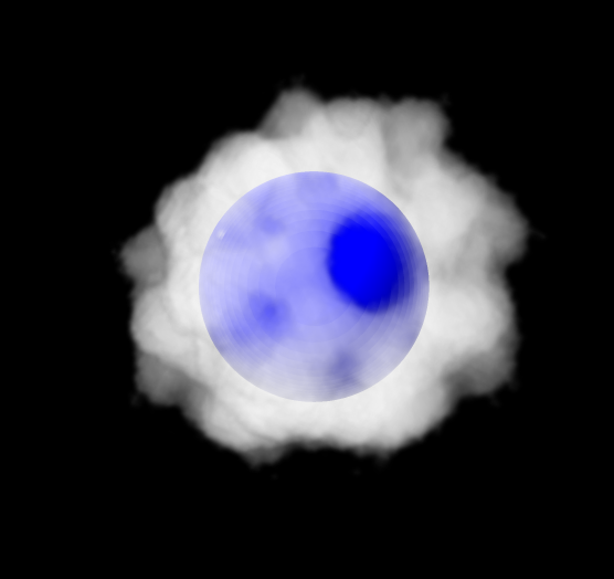
comment:5 by , 2 years ago
I've attached an image illustrating how an opaque blue sphere occludes parts of a volume rendering made with commands
open 1080 from emdb
volume #1 style image
shape sphere radius 50 color blue
and twiddling with the threshold levels in the Volume Viewer.
by , 2 years ago
| Attachment: | image1.png added |
|---|
Example image of opaque object occluding volume image rendering.
comment:6 by , 2 years ago
Replying to Tom Goddard:
Are you talking about your raytracing rendering? Because the standard ChimeraX volume rendering depth tests and the shows the part of a volume rendered map in front of opaque objects, while the part behind opaque objects is not visible.
This is going to be harder to achieve with ray casting since the fragment shader will have to do depth buffer tests as Greg says in the previous comment. I'm not sure if that can be done unless the depth buffer is written to a texture.
I think you are correct. Suppose as a subproject that builds towards this one, I wanted to display the depth buffer for debugging purposes. This code works, but I wonder if you have any comments on it:
# class Render: ...
    def _draw_depth_buffer(self):
        t = Texture()
        fb = self.current_framebuffer()
        t.initialize_depth((fb.width, fb.height))
        tw = self._texture_window(t, self.SHADER_SHOW_DEPTH_BUFFER)
        GL.glReadBuffer(GL.GL_BACK)
        GL.glCopyTexImage2D(GL.GL_TEXTURE_2D, 0, GL.GL_DEPTH_COMPONENT, 0, 0, fb.width, fb.height, 0)
        p = self.current_shader_program
        p.set_integer("depth_texture", 0)
        tw.draw()
        t.unbind_texture()
        t.delete_texture()
comment:7 by , 2 years ago
I don't have any comments about copying the depth buffer to a texture.
But what is the goal of the raycasting? From what I have seen of your current effort it does gradient-based lighting by sampling a 3D texture. That could be done with a few extra lines of code in the current plane-based fragment shader. So why all the extra complexity, like doing your own depth testing, and figuring out rays to cast?
comment:8 by , 2 years ago
I see two advantages of raycasting: speed and quality.
On speed: I copied the gradient calculation from the racyasting loop into the USE_LIGHTING clause of the fragment shader.
#ifdef USE_LIGHTING_NORMALS
    // Unit normal, with two-sided lighting.
    vec3 N1 = normalize(N) * (gl_FrontFacing ? 1.0 : -1.0);
    // vec3 N1 = normalize(N);  // single-sided lighting
    // Unit vector from camera to surface point.
    vec3 v1 = normalize(v);

    float key_factor = max(-dot(N1,key_light_direction),0.0);
    float fill_factor = max(-dot(N1,fill_light_direction),0.0);
    vec3 R = normalize(reflect(key_light_direction,N1));
    float specular_factor = pow(max(-dot(R,v1),0.0), key_light_specular_exponent);
  #else
    #ifdef USE_TEXTURE_3D
    vec3 N1 = normalize(vec3(
            texture(tex3d, tex_coord_3d + vec3(0.01, 0.0, 0.0)).r - texture(tex3d, tex_coord_3d - vec3(0.01, 0.0, 0.0)).r,
            texture(tex3d, tex_coord_3d + vec3(0.0, 0.01, 0.0)).r - texture(tex3d, tex_coord_3d - vec3(0.0, 0.01, 0.0)).r,
            texture(tex3d, tex_coord_3d + vec3(0.0, 0.0, 0.01)).r - texture(tex3d, tex_coord_3d - vec3(0.0, 0.0, 0.01)).r
        ));

    float key_factor = max(-dot(N1,key_light_direction),0.0);
    float fill_factor = max(-dot(N1,fill_light_direction),0.0);
    vec3 R = normalize(reflect(key_light_direction,N1));
    float specular_factor = 0;
    #else
    float key_factor = 1;
    float fill_factor = 1;
    float specular_factor = 0;
    #endif
  #endif
I omitted the specular factor because it would require calculating the ray direction, and at that point you may as well raycast. Then I opened a dataset from TCIA:
open 61.7.259229997858724420813408711235467205350 format dicom fromDatabase tcia
and turned on lighting in the Python shell (session.models[-1]._drawings[0].use_lighting = True)
In raycasting, we do this gradient calculation for each sample along the ray and accumulate color and opacity as we go. This lets us either exit early if the alpha along the ray gets close enough to or exceeds 1.
Without any early termination or space skipping, the performance goes down by about 40% compared to raycasting (19fps vs 31fps with the default thresholds).
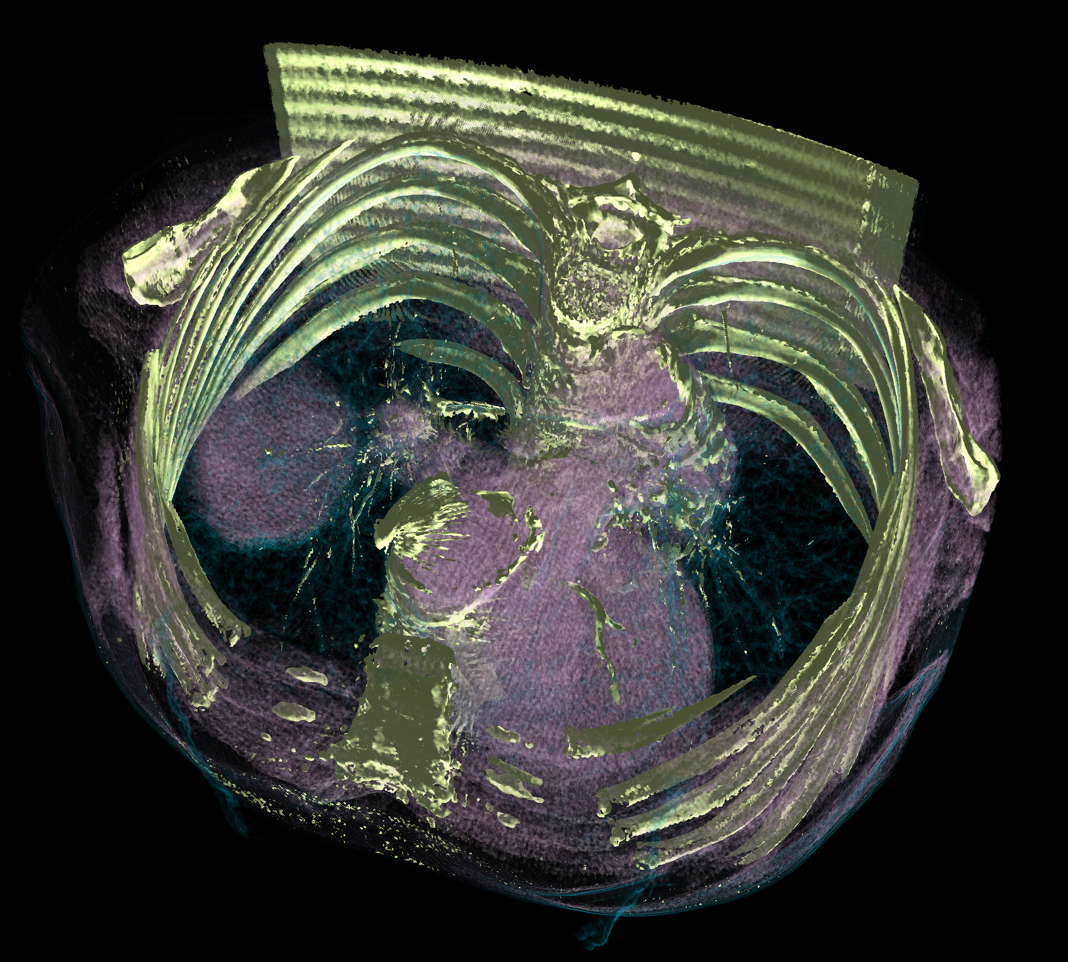
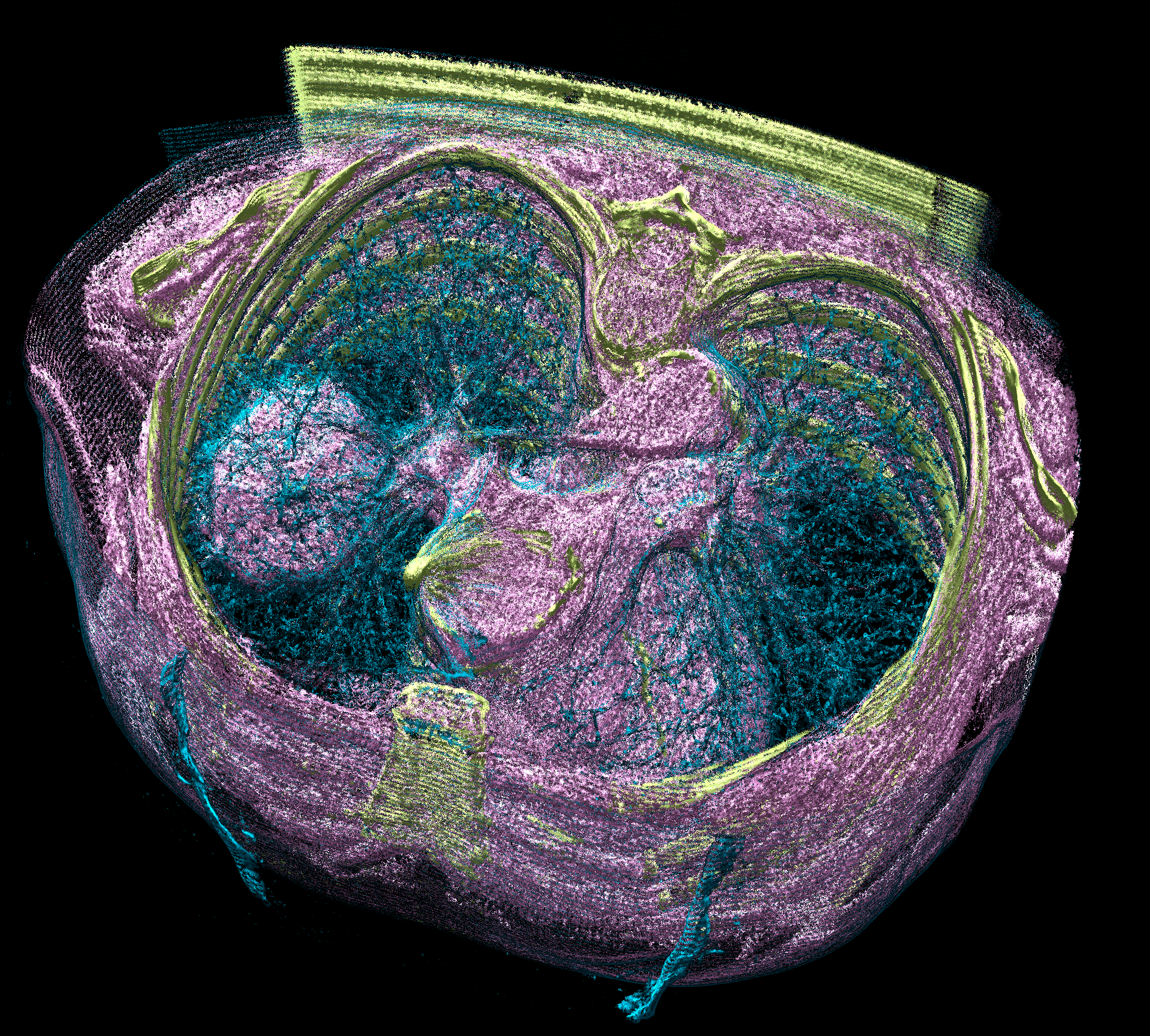
On quality: It's really a tossup and very subjective. Texture mapped drawings with lighting look really good when depicting hightly opaque regions because they're smoother than the raycasting. On the other hand, I think raycasting captures more detail and there are techniques to make the picture smoother. I attached a couple screenshots that I think are a fair comparison of a lung tumor. I think they show what I've said: the surfaces in the texture mapped images are much more pleasing and smooth, but the raycast image captures much more detail.
by , 2 years ago
| Attachment: | Screenshot 2024-08-07 at 14.33.25.png added |
|---|
Texture mapping with lighting
comment:9 by , 2 years ago
These images are actually from the data opened using open 1.3.6.1.4.1.9328.50.1.298748100008818908989408006815250397386 format dicom fromDatabase tcia, which I decided halfway through writing that comment was a better dataset to use, and I set the specular factor in the raycasting shader to 0 for fairness.
comment:10 by , 2 years ago
Ok glad you are thinking about it. Speed and quality are important images. I think speed essentially comes down to the number of texture look-ups so basically you increase speed by decreasing quality. Raycasting I think would have advantages in smoothly changing that balance. But I am interested in why quality would be better. Your images appear to show that opacity is handled differently in the two approaches you compared. It is easy to adjust opacity mapping in either approach and it is good to figure out what gives the best appearance and to give the user control over that.
When the opaque surface is drawn, it sets the depth buffer. The transfer function needs to take that saved depth into account if it isn't already. Perhaps it's not being drawn during the transparent phase?